|
|
Bachelor's Degree in Telecommunications Systems and in Network Engineering |
|
CSD products |
This is a detailed list of materials for helping you to study and design projects and thus, passign the course without complications. Please, get used to ask us as many questions as necessary.
| Analysis and design tutorials | Analysis and design assignments | Questions | Exam 1 | Exam 2 | Assessment |
Chapter 1 analysis of circuits based on logic gates:
| AT1.1 | Circuit_C (P1) | AT1.2 | Circuit_W, (Lab1.1) |
| AT1.3 | Circuit_W, (Lab1.2) | AT1.4 | Circuit_K |
| AT1.5 | Circuit_P | AT1.6 | Circuit_Q |
Chapter 2 analysis of synchronous and asynchronous circuits based on flip-flops and logic:
| AT2.1 | Circuit_Async | AT2.2 | Circuit_Sync1 (update) |
| AT2.3 | Circuit_Async2 Highlighted P5 project | AT2.4 | Circuit_Async4 (update) |
| Analysis and design tutorials | Analysis and design assignments | Questions | Exam 1 | Exam 2 | Assessment |
Chapter 1 and 3 design projects of combinational circuits
In Chapter 3 these circuits are used to learn basic digital input and output.
| Plan A: structure, equations | Plan B: behavioural, truth table | Plan C2: hierarchical structure | |
| DT1.1 | Circuit_C Highlighted P1 project | ||
| DT1.2 | Circuit_K | Circuit_K | Circuit_K |
| DT1.3 | Circuit_P | Circuit_PQ | Circuit_PQ |
| DT1.4 | Circuit_Q | ||
| DT2.1 | MUX_8,(Lab2) | MUX_8, (Lab2) | MUX_8 Optional: MUX_8 using plan C1 |
| DT2.2 | MUX_16 | ||
| DT2.3 | DeMUX_16 | ||
| DT2.4 DT9.1 |
Dual_MUX_4 | Dual_MUX_4 Dual_MUX_4 (μC I/O basics) (Lab9) |
Dual_MUX_4 |
| DT2.5 | Quad_MUX_2 / Quad_MUX_4 | ||
| DT2.6 | Dec_3_8 | Dec_3_8 | Rec. on Dec_3_8 |
| DT2.7 | Dec_4_16 | Dec_4_16 | |
| DT2.8 | Hex_7seg_decoder Highlighted P2 project | Hex_7seg_decoder Dec_hex_7seg | |
| DT2.9 | Enc_10_4 | Enc_10_4 | Enc_10_4 using Enc_8_3 |
| DT2.10 | Tank_level_meter | Tank_level_meter | |
| DT2.11 | Bin_BCD_6bit | Bin_BCD_6bit includes the DM74185 | |
| BCD_bin_mod40 | |||
| DT3.1 | Bin_BCD_9bit | ||
| DT3.2 | Bin_BCD_16bit | ||
| DT3.3 | Comp_1bit | Comp_1bit | Comp_1bit using the MoM |
| DT3.4 | Comp_4bit | Comp_4bit | |
| DT3.5 | Comp_10bit | ||
| DT3.6 | Adder_1bit | Adder_1bit |
Adder_1bit MoD Adder_1bit MoM, (Lab3) |
| DT3.7 | Rec. on Adder_2bit | ||
| DT3.8 |
Ones_counter_8bit
Highlighted P3 project Ones_counter_4bit |
||
| DT3.9 |
Adder_4bit carry lookahead (CLA) Adder_4bit ripple carry (RC) |
||
| DT3.10 | Adder_8bit, (Lab3) | ||
| DT3.11 |
Adder_16bit,
(RC) (Lab4) Adder_16bit, (CLA) (Lab4) |
||
| DT9.2 DT11.1 |
Adder_BCD_1digit
(P9)
(design phase #1) Adder_BCD_1digit_LCD (design phase #2) |
||
| DT3.11 | Mult_9bit | ||
| DT4.1 | Int_add_subt_8bit Highlighted P4 project | ||
| DT4.2 | |||
| DT4.3 | Int_Mult_9bit | ||
Chapter 2 and 3 design tutorials on FSM
Design tutorials of sequential circuits (FSM) plan C1. In Chapter 3 these circuits are used for learning interrupts and microcontroller applications:
| DT6.1 | D_FF , D-type flip-flop | ||
| DT6.2 | JK_FF, JK flip-flop (also an RS-flip-flop) | ||
| DT6.3 | T_FF, Toggle flip-flop | ||
| DT6.4 | Matrix_encoder_16key Highlighted P6 project | ||
| DT6.5 | Light_control, classroom luminaries, (Lab6) | ||
| DT6.6 | LED bicycle torch | ||
| DT6.7 | Debouncing_filter, low-pass filter and synchroniser. | ||
| DT6.8 | Traffic light controller | ||
| DT10.1 | Design phase #1 | Serial_transmitter (P10) | |
| DT11.2 | Design phase #2 | Serial_transmitter_LCD (P11) | |
| DT12.1 | Design phase #3 | Serial_transmitter_LCD_TMR0 (P12) | |
| DT12.2 | Design phase #4 | Serial_transmitter_LCD_TMR2 | |
Chapter 2 and 3 design tutorials on counters and registers
| Plan X: FSM, state enumeration | Plan Y: FSM, large number of states | Plan C2: hierarchical structure | |
| DT7.1 DT10.2 |
Counter_BCD_1digit | Counter_BCD_1digit | |
| Counter_BCD_1digit, (Lab10), (design phase #1) | |||
| DT11.3 | Counter_BCD_1digit_LCD (design phase #2) | ||
| DT12.3 | Counter_BCD_1digit_LCD_TMR0 (design phase #3) where TMR0 as counter replaces INT0. | ||
| DT10.3 |
Counter_mod_1572,
(Lab10) Counter_mod1572 |
||
| DT7.2 | Counter_mod12 | Counter_mod12, (Lab7) | Counter_mod12, (Lab7) |
| DT7.3 | Counter_mod16 (versatile chip) | ||
| DT7.4 | Hour_counter (P7) | ||
| DT7.5 | Counter_BCD_mod60 | ||
| DT7.6 | Data_reg_4bit | ||
| DT7.7 | Shift_reg_4bit | ||
| DT10.4 | Johnson_sequencer_mod12 (design phase #1) | ||
| DT11.4 | Johnson_sequencer_mod12_LCD (design phase #2) | ||
| DT12.4 | Johnson_sequencer_mod12_LCD_TMR0 (design phase #3) | ||
| DT7.7 | counter_BCD_2digit.pdsprj (modulo 100) in Proteus, plan C2, chaining two 1-digit BCD counters | ||
Chapter 2 and 3 design tutorials on dedicated processors
| DT8.1 |
Timer_MMSS
(P8) Timer_MMSS |
||
| DT8.2 | Mult_4bit serial multiplier | ||
| DT8.3 | Adder_4bit serial adder | ||
| DT8.4 |
USART universal serial async receiver &
transmitter USART |
||
| DT12.5 | Design phase #1 | Timer, (Lab11) | |
| DT12.6 | Design phase #2 | Timer_LCD, (Lab11) | |
| DT12.7 | Design phase #3 | Timer_LCD_TMR0, (Lab11) | |
| DT12.8 | Design phase #4 | Timer_LCD_TMR2 | |
| DT12.9 | (Arduino) | Temp_meter | |
| DT12.10 | (Arduino) | Tap_control |
| Analysis and design tutorials | Analysis and design assignments | Questions | Exam 1 | Exam 2 | Assessment |
Chapter 1 analysis assignments
| A1.1 | Circuit_L | A1.2 | Circuit_U |
| A1.3 | Circuit_VT | A1.4 | Circuit_M |
| A1.5 | Circuit_N | A1.6 | Circuit_G |
| A1.7 | Circuit_R | A1.8 | Circuit_Z |
| A1.9 | Circuit_Y |
Chapter 2 analysis assignments
| A2.1 | Circuit_E (sync) | A2.2 | Circuit_A (async) |
| A2.3 | Circuit_D (async) | A2.4 | Circuit_I (async) |
| A2.5 | Circuit_F (sync) | A2.6 | Circuit_B (async) |
| A2.7 | Circuit_C (async) | A2.8 | Circuit_G (async) |
| A2.9 | Circuit_H (async) |
| Analysis and design tutorials | Analysis and design assignments | Questions | Exam 1 | Exam 2 | Assessment |
Chapter 1 and 3 design assignments
| D1.1 | B3.1 | Wind compass | D1.2 | B3.2 | BCD_7seg_decoder chip | |
| D1.3 | B3.3 | 5-bit ones counter | D1.4 | B3.4 | From P1: Circuit_VT, Circuit_G, Circuit_U | |
| D1.5 | B3.5 |
|
D1.6 | B3.6 | Water tank level meter (9 sensors) | |
| D1.7 | B3.7 | 2-digit multiplexed 7-segment display | D1.8 | B3.8 | 5-bit Gray to binary converter | |
| D1.9 | B3.9 | 4-bit (nibble) shifter operator | D1.10 | B3.10 | 4-bit binary to Johnson converter | |
| D1.11 | B3.11 | Sel _add_subt_comp_10bit | D1.12 | B3.12 | 16-bit comparator for integer numbers | |
| D1.13 | B3.13 | 8-bit subtractor using Subtractor_1bit | D1.14 | B3.14 | 9-bit parity generator, parity checker | |
| D1.15 | B3.15 | BCD_bin_3digit, code converter | D1.16 | B3.16 | Bin_BCD_9bit, code converter | |
| D1.17 | B3.17 | 2-digit BCD adder | D1.18 | B3.18 | ALU_12bit | |
| D1.19 | B3.19 | Parking occupancy (32-bit ones counter) | D1.20 | B3.20 |
Chapter 2 and 3 design assignments
| D2.1 | D3.1 | CD player buttons | D2.2 | D3.2 | Stepper motor controller |
| D2.3 | D3.3 | Designing a LED rotator | D2.4 | D3.4 | Pattern detector (versions 1 and 2) |
| D2.5 | D3.5 | LED dimmer | D2.6 | D3.6 | 7-segment digit sequencer |
| D2.7 | D3.7 | Dumbwaiter or simple lift | D2.8 | D3.8 | Electronic keypad lock (versions A and B) |
| D2.9 | D3.9 | Water tank controller | D2.10 | D3.10 | Vending machine |
| D2.11 | D3.11 | Wireless IR TV remote control | D2.12 | D3.12 | Electronic roulette |
| D2.13 | D3.13 | 3-digit programmable BCD down counter | D2.14 | D3.14 | Traffic light controller |
| D2.15 | D3.15 | 16-key matrix encoder with handshake | D2.16 | D3.16 | Scale (BCD up counter modulo 50000) |
| D2.17 | D3.17 | Shower stall automation | D2.18 | D3.18 | Morse code generator |
| D2.19 | D3.19 | Washing machine controller | D2.20 | D3.20 | Chip 74HC4017 (5-bit Johnson counter) |
| D2.21 | D3.21 | Programmable timer | D2.22 | D3.22 | Bit pattern generator |
| D2.23 | D3.23 | Earbuds control buttons | D2.24 | D3.24 | Rotation speed meter (tachometer) |
Laboratory prototypes and PCB for soldering and measuring
Circuit_W (Lab1_2), MUX_DeMUX (Lab2), Dec_Hex_7seg (DE10-Lite), ALU_9bit (Lab4_2), CSD_PICstick.
| Analysis and design tutorials | Analysis and design assignments | Questions | Exam 1 | Exam 2 | Assessment |
- Sample questionnaire Q1_4 on P1, P2, P3 and P4 projects.
- Sample questionnaire Q5_8 on P5, P6, P7 and P8 (content from all previous projects is included).
- Sample questionnaire Q9_12 on P9, P10, P11 and P12 projects (content from all previous projects is included).
| Analysis and design tutorials | Analysis and design assignments | Questions | Exam 1 | Exam 2 | Assessment |
- 2324Q2 pdf and solution ideas.
- 2324Q1 pdf and solution ideas. Prob1 circuit in Proteus.
- 2223Q2 pdf and solution ideas.
- 2223Q1 pdf and example solutions.
- 2122Q2 pdf and example solutions Prob1, Prob2.
- 2122Q1 pdf and example solutions. Prob1 and Prob4 in Proteus.
- 2021Q2 pdf and example solutions. Prob1 in Proteus (Version 8.12)
- 2021Q1 pdf and example solutions.
- 1920Q1 pdf and example solutions.
- 1819Q2 pdf and example solutions (Prob. 1 option B is here as the Circuit_Q).
- 1819Q1 pdf and discussed solutions (Prob1) (Prob2).
- 1718Q2 pdf and a discussed solution. This is the Problem 1 truth table in Minilog format.
- 1718Q1 pdf and a Proteus simulation to experiment the way it works, and a possible solution. The Gray_Bin_Converter (Chip1) in Minilog format.
- 1617Q2 pdf that contains many concepts develop since now through P1 .. P4. This is the Proteus file, the truth table in Minilog and the results when simplifying by PoS.
- 1617Q2 pdf. The truth table and the symbol in Proteus that can be simulated attaching this "jed" to the AM22V10 sPLD. This is a VHDL file using plan B (question 5), and this is the ispLEVER Classic report where you see the pin connections after synthesising the circuit.
| Analysis and design tutorials | Analysis and design assignments | Questions | Exam 1 | Exam 2 | Assessment |
- 2324Q2 pdf and solution ideas. P1 in Proteus (method II).
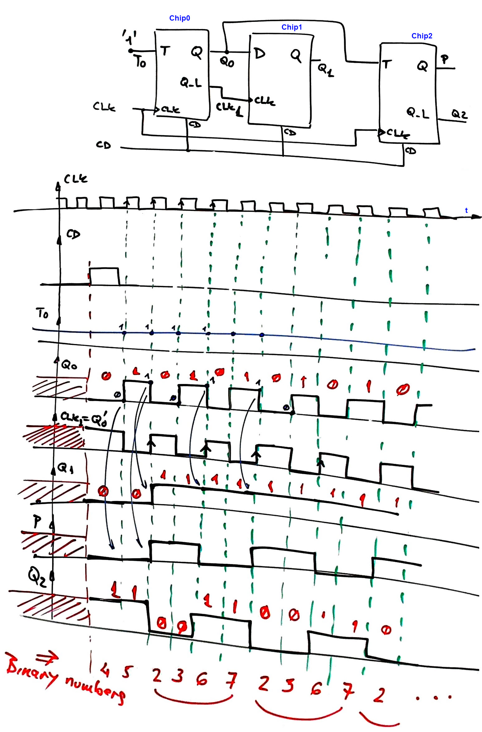
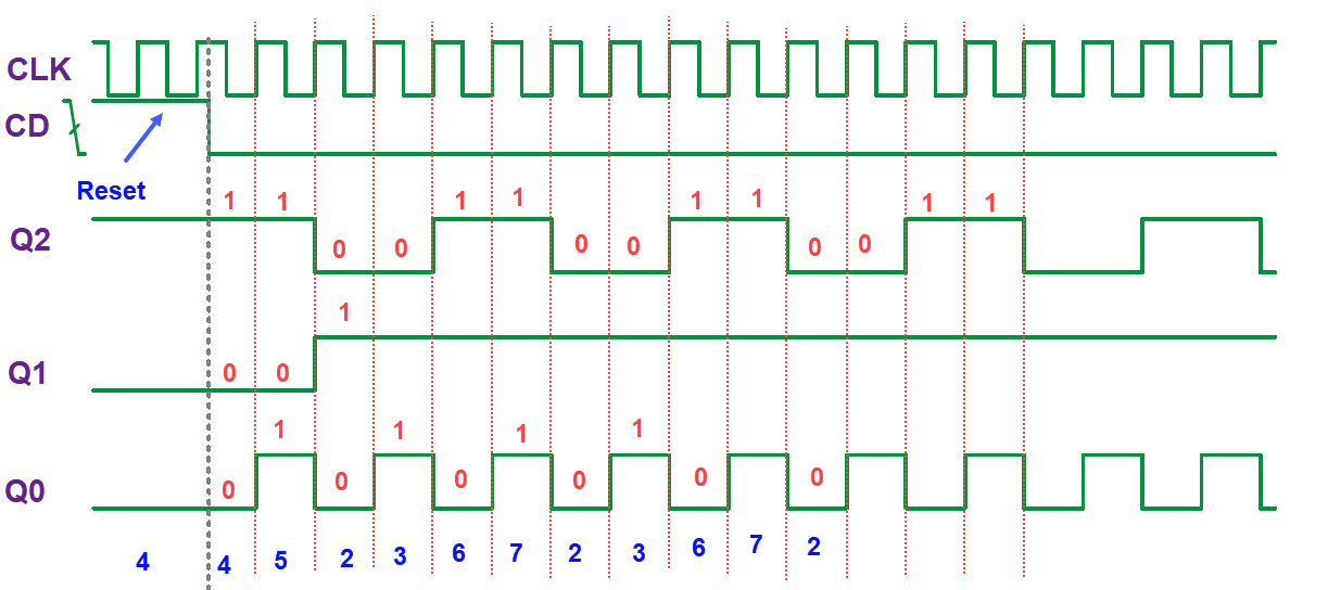
- 2324Q1 pdf and solution ideas. P1 analysis (method I). P1 in Proteus (method II) to check the analytical result and edited printed output waves.
- 2223Q2 pdf and solution ideas. Question 10 async circuit in Proteus.
- 2223Q1 pdf and solution ideas. Prob1 in Proteus to check the analytical result.
- 2122Q2 pdf and solution ideas.
- 2122Q1 pdf and example solutions. Prob1 in Proteus. P1 in VHDL.
- 2021Q2 pdf and example solutions. Prob1 in Proteus.
- 2021Q1 pdf and example solutions (Prob1 - Proteus, Prob2, and Prob3 - Proteus).
- 1920Q2 pdf and example solutions.
- 1920Q1 pdf and example solutions.
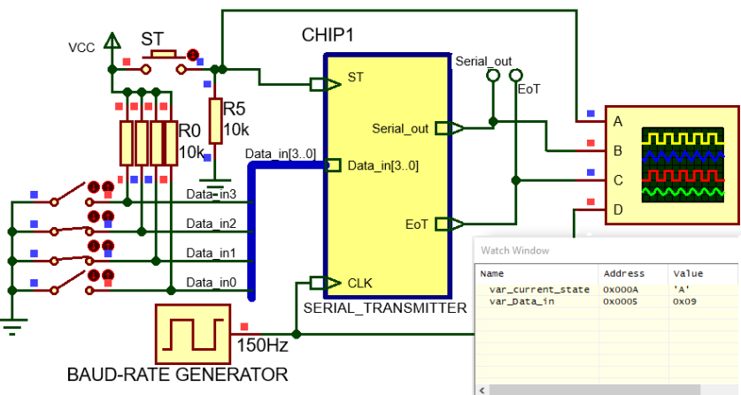
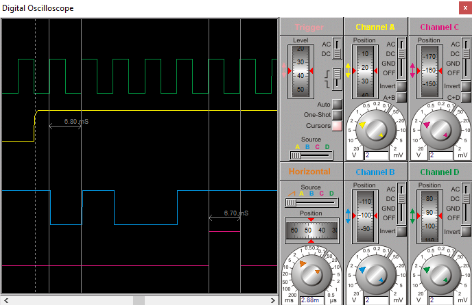
- 1819Q2 pdf and example solutions (Prob1-Prob2) (Prob3, this is a tutorial solution on specifications and planning, like class notes. This is an example project in Proteus for the serial transmitter (Circuit, waves. This Prob3 is a kind of introduction for projects such N.15 where the USART peripheral is used for serial RS232 transmissions).
- 1819Q1 pdf and example solutions (Prob1) (Prob2).
- 1718Q2 pdf and a draft solution example (Prob1, Prob2, Prob3).
- 1718Q1 pdf and a draft solution example.
| Analysis and design tutorials | Analysis and design assignments | Questions | Exam 1 | Exam 2 | Assessment |
Continuous assessment of student achievement
CSD scheme of continuous assessment (grading sheet): 17 items, 11 of which include weekly formative feedback and discussion. Your partial grades will be available and updated at Atenea platform.
- P_Ch1 => 15% of the final grade,
(individual) PLA1.1 (10%) + PLA1.2 (20%) +
(group work) PLA2 (10%) + PLA3 (report + video, 40%) + PLA4.1 (10%) + PLA4.2 (10%)
- P_Ch2 => 6% of the final grade, (group work), PLA6 (50%) + PLA7 (report + video, 50%)
- P_Ch3 => 9 % of the final grade, (group work) , PLA9 (20%) + PLA10 (30%) + PLA11 (work in progress + report + video, 50%)
- Classroom activities => 8%
- Q1-4 => 4%; Q5-8 => 4%; Q9-12 => 4%
| Home Term 24/25-Q1 Contact Products Electronic devices and companies Software Books Magazines Instruments DEE Library EETAC DEEL |

|
|
| Web activa des de 09/2001, @ F. J. Robert, J. Jordana. Web editat amb Microsoft Expression Web 4. El contingut és un complement als materials d'estudi del curs Circuits i Sistemes Digitals disponibles al campus digital Atenea. Llicència:Reconeixement 4.0 Internacional de Creative Commons |