|
|
Bachelor's Degree in Telecommunications Systems and in Network Engineering |
|
|
|
|||||
Chapter 2 problems |
- D2.19 - |
Washing machine controller (FPGA-VHDL) |
|||
|
|
|||||
1. Specifications
Washing machines are perfect examples of sequential systems. They are complex systems due to the number of sensors, buttons and the many operating modes and actuators. References and full schematics on how this home appliance works and be be designed can be found in pages such: Explainthatstuff 1, Toshiba 2 - 3 , Samsung 4, research journals 5.
The same project designed programming a μC is in D3.19.
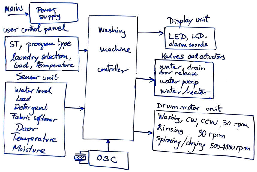 |
| Fig. 1. Block diagram of the main units of a modern washing machine (ref. 5). |
In CSD we can imagine inventing the washing machine controller in successive design phases (some of them out of the scope of this introductory course). For example:
-
Design phase #1: Basic operation, assuming only a few sensors and actuators. The idea is to setup the FSM architecture.
-
Design phase #2: Add to the controller a programmable timer for setting wash, rinse and spin/dry cycle timings. Thus, converting the FSM into a dedicated processor.
-
Design phase #3: Add water level, temperature, moisture and other sensors to automate some cycles in function of drum load. Add door-blocking mechanism and drain filter clogging alarm detector.
-
Design phase #4: Full automation with keypad and display for laundry fabric types and colours (cotton, wool, silk, synthetic, etc.) and even special cycles for extremely dirtied items or medium loads or cold water only.
Design phase #1
1. Specifications
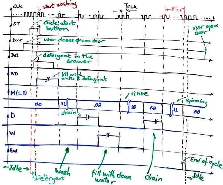
Let us imagine a washing machine assuming for simplicity the same duration for all machine cycles to be of 8·TCLK: fill water with detergent, wash, drain, fill clean water, rinse, drain, spin.
 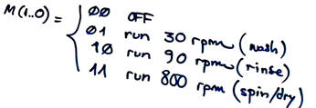 |
Fig. 2. Washing machine controller. |
When the user clicks start (ST) button the controller fills the drum with warm water when the door is closed and detergent is detected in the drawer. The motor agitates the drum clockwise CW and counter clockwise (CCW) until the washing cycle is finished. Rinsing starts after the dirty, soapy water is drained and the washing machine is refilled with clean water to wash clothes again. Once the water is drained completely, laundry is spun very fast and excess water is removed thanks to centrifugal force. While operating the machine cannot be stopped.
Visualise the sequence of washing operations using a timing diagram.
 |
|
Fig. 3. Washing machine timing diagram. |
2. Planning
Design Washing_controller chip applying FSM methodology.
For instance, using the architecture shown in Fig. 4 based on two components (FSM and Counter_mod8) interconnected using signals (TC, CC)
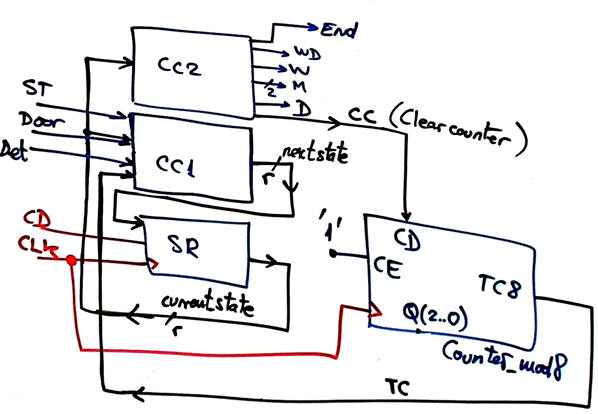 |
| Fig. 4. Architecture requiring a counter to set time for washing machine cycles. This counter is replaced in desigh phase #2 by programmable counters and sensor inputs. |
In Fig. 5 there is an example of state diagram to drive all outputs and conrol the counter.
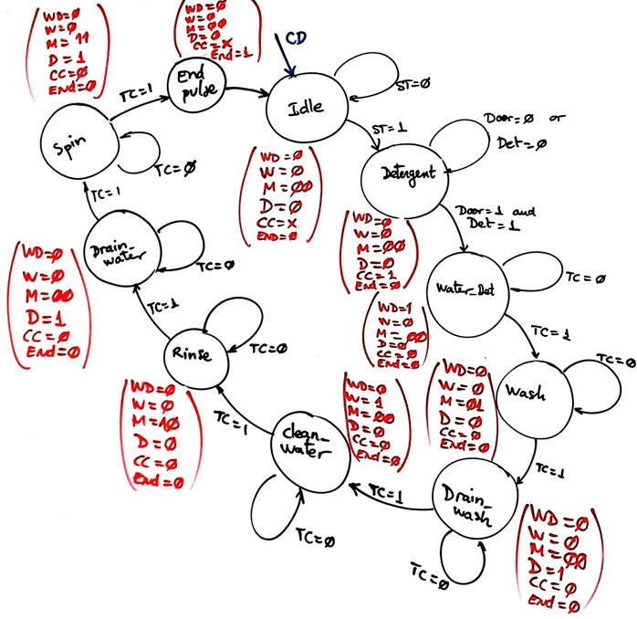 |
Fig. 5. Example of state diagram. |
Apply the design sequence FSM to obtain the circuit and test it.
| Home Term 24/25-Q1 Contact Products Electronic devices and companies Software Books Magazines Instruments DEE Library EETAC DEEL |

|
|
| Web activa des de 09/2001, @ F. J. Robert, J. Jordana. Web editat amb Microsoft Expression Web 4. El contingut és un complement als materials d'estudi del curs Circuits i Sistemes Digitals disponibles al campus digital Atenea. Llicència:Reconeixement 4.0 Internacional de Creative Commons |