|
|
Bachelor's Degree in Telecommunications Systems and in Network Engineering |
|
|
|
Design Circuit_Q using plan A |
Circuit_Q plan B |
Circuit_Q plan C2 |
| 1. Specifications | Planning | Developing | Testing | Report | Prototype |
Using Circuit_Q truth table written in Fig. 1 invent the following equivalent circuits using gates (plan A):
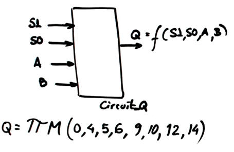 |
Fig. 1. Circuit_Q symbol and truth table deduced from the analysis project above. |
- Circuit_Q1. Draw the equivalent circuit using sum of minterms. Check it using method III on VHDL.
- Circuit_Q2. Design an equivalent minimised circuit based on PoS. Check it using method IV on WolframAlpha
| Specifications | 2. Planning | Developing | Testing | Report | Prototype |
From the Circuit_Q truth table we can obtain different circuits. For instance:
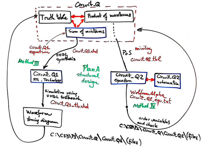 |
| Fig. 2. Concept map for designing alternative circuits from the initial truth table. Set as well the project locations. |
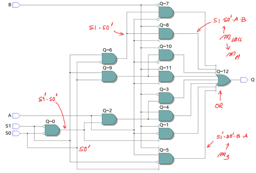
1. Circuit_Q1. Use the sum of minterns expression to draw the circuit composed of a regular network of BUFFER-NOT - AND - OR. All AND gates (minterms) are 4 inputs. A single OR gate is required. We obtain a regular circuit of three levels of gates.
2. Circuit_Q2. Use minilog to minimise Q = f(S1, S0, A, B) as a SoP and draw the circuit.
| Specifications | Planning | 3. Developing | Testing | Report | Prototype |
Circuit_Q1 is drawn from its initial sum of minterms equation:
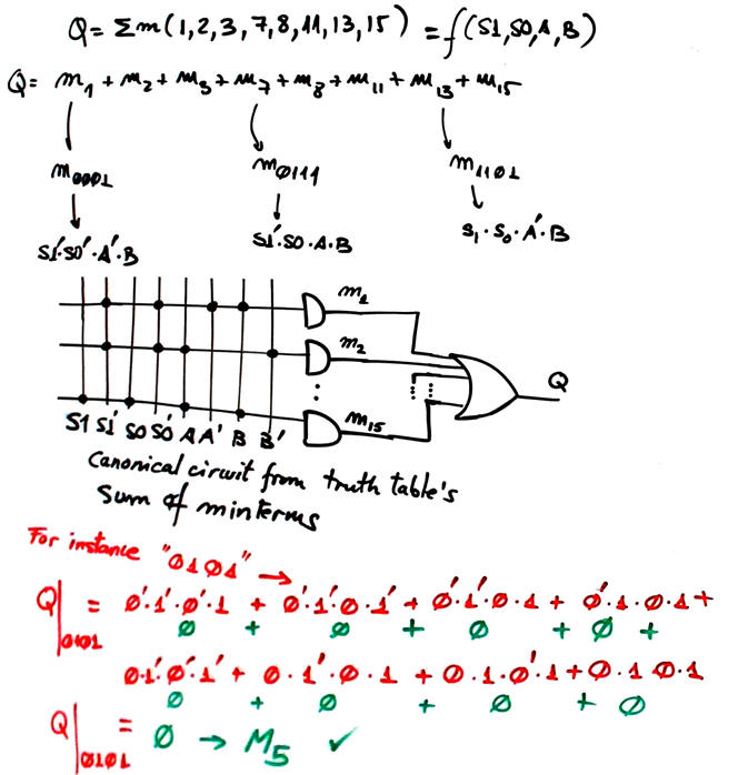 |
| Fig. 3. Circuit_Q1 created directly from the sum of minterms canonical equation that defines the truth table. |
Circuit_Q2. Run minilog from Circuit_Q2.tbl and draw the circuit based on PoS
 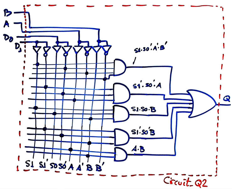 |
| Fig. 4. Circuit_Q2 created using the minimised equation SoP. |
| Specifications | Planning | Developing | 4. Testing | Report | Prototype |
Circuit_Q1. Method III. Let us select a MAX10 10M50DAF484C7 Intel FPGA chip for translating the project to VHDL. Circuit_Q1.vhd.
  |
| Fig. 5. RTL and technology circuits. Be aware how the Quartus Prime embedded synthesiser tool using default parameters implements another simpler equation intead of the sum of minterms ideally described in the RTL view. |
Circuit_Q1 is tested using ModelSim functional simulations from this Circuit_Q1_tb.vhd.
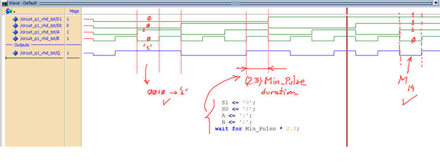 |
| Fig. 6. Simulation results for determining and verifying the circuit's truth table. All the input combinations generates |
Circuit_Q2. Method IV. Let translate the minimised SoP equation to WolframAlpha Circuit_Q2_equ.txt and get results running the engine. Be aware that depending of the variable order when writing the equation, you have to reorder aswell the output table to identify correctly the set of minterms and maxterms.
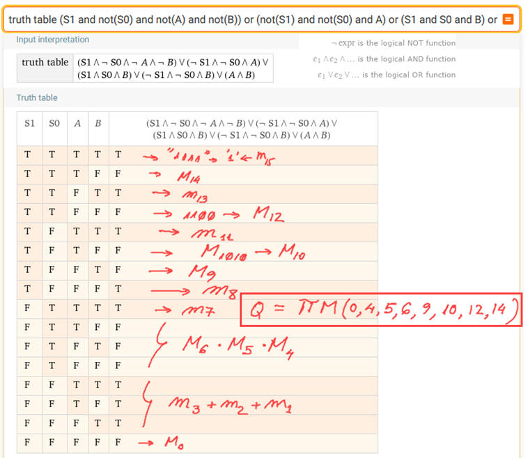 |
| Fig. 7. Table results from WolframAlpha. |
| Specifications | Planning | Developing | Testing | 5. Report | Prototype |
Follow this rubric for writing reports.
| Specifications | Planning | Developing | Testing | Report | 6. Prototype |
We can use the DE10-Lite board to implement this project, as shown in Lab 1.2 for the similar Circuit_W.
| Home Term 26/27-Q1 Contact Products Electronic devices and companies Software Books Magazines Instruments DEE Library EETAC DEEL |

|
|
| Web activa des de 09/2001, @ F. J. Robert, Web editat amb Microsoft Expression Web 4. El contingut és un complement als materials d'estudi del curs Circuits i Sistemes Digitals disponibles al campus digital Atenea. Llicència:Reconeixement 4.0 Internacional de Creative Commons |