|
|
Bachelor's Degree in Telecommunications Systems and in Network Engineering |
|
|
|
|||
|
|
Arduino-based tap control using an ultrasonic sensor |
|
|
|
|
|||
Signal acquisition, ultrasonic sensor, distance measurement, FSM, Raspberry Pi
1. Specifications
Design a tap control circuit based on an ultrasonic sensor. When an obstacle is found in front of the sensor, let us say at less than 40 cm, the tap is switch on. Water flow stops automatically after 10 s.
A simpler version of this project intended for primary or secondary schools is presented in this aixeta page.
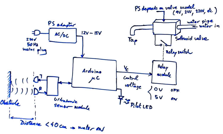 |
Fig. 1. A sketch showing the controller main components. |
 |
|
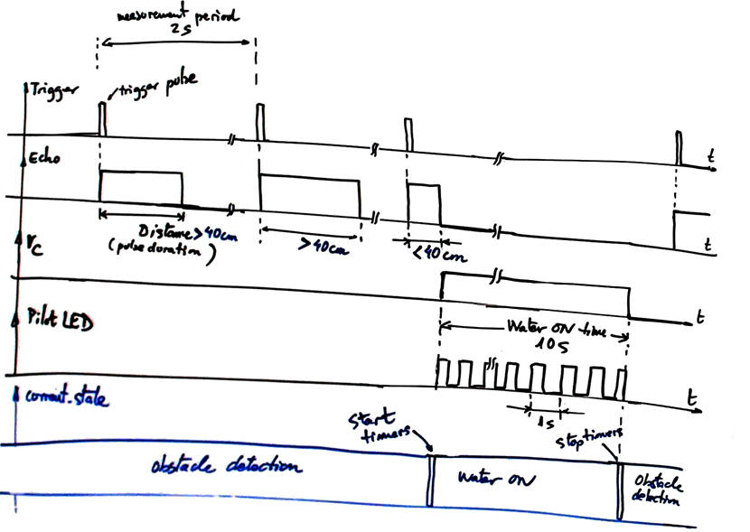
Fig. 2. Timing diagram. The device measures continuously until a distance to an obstacle is detected less than 40 cm. |
2. Planning
A) Planning hardware
Step 1: Hardware.
An ultrasonic sensor may be HC-SR04. It has been simulated as a subcircuit in Proteus.
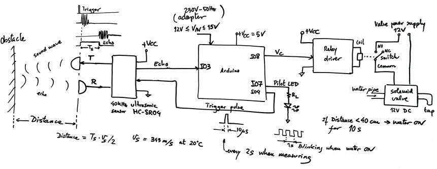 |
| Fig. 3. Example of proposed circuit. Once the obstacle detected, the relay is timed for 10 s allowing the water flow. When the distance is larger than 40 cm, water tap is off and the system measures distance periodically every 2 s. |
B) Planning software
An state diagram is represented in
FSM architecture. RAM variables.
 |
|
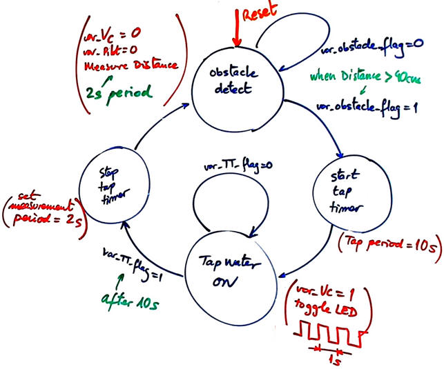
Fig. 4. State diagram with two main states: tap OFF and tap ON, and another two auxiliary ones for initializing and stopping timers. |
The main function in this application datapath() is for performing distance measurements and detecting when distances to obstacles are shorter than 40 cm. Pulse duration will be measured using external interrupt INT1 triggered on change events (rising and falling edges). In Arduino UNO only pin 2 (INT0) and pin 3 (INT1) can be used as external interrupts.
 |
|
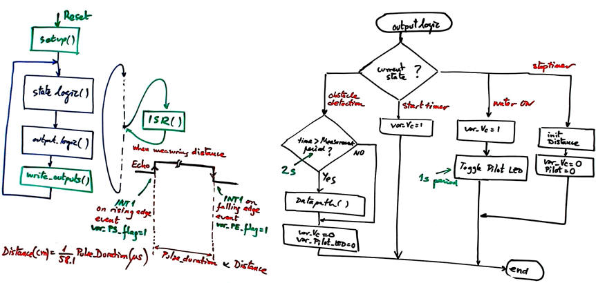
Fig. 5. The main program as a FSM and the function output_logic(). Datapath() is only required in state obstacle detection. |
The FSM organisation allows maximum speed loop execution with no unnecessary delays. Discuss about how many time the application is doing nothing, so that extra features such LCD or other sensors can be attached. How to sleep the FSM to save energy?
 |
|
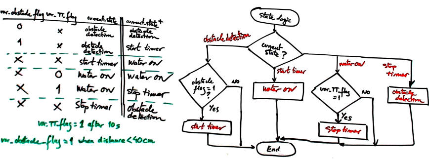
Fig. 6. The function state_logic() implements the state transitions using flags from the ultrasonic sensor and timers. |
The key status signal var_obstacle_flag is processed by the datapath () using interrupts.
 |
|
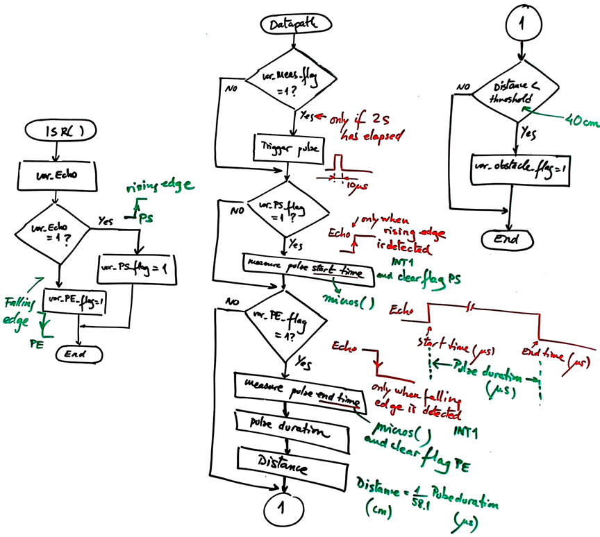
Fig. 6. The function datapath() to perform distance calculations to detect obstacles. Interrupt service routine reads the level of the Echo signal and determines whether the even has been on rising or falling edge. |
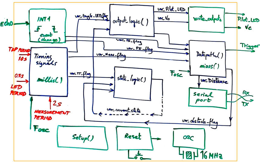
Perhaps, the hardware-software diagram represented in Fig. 6 allows a better comprehension of the system architecture.
 |
|
Fig. 6. Hardware and software diagram. |
Target chip and tools: Arduino, Arduino IDE or Proteus VSM for Arduino. Project location:
C:\CSD\P12\Tap\(files)
3. Step by step developing and (4) testing
A) Developing hardware
We can generate a sensor simulator subcircuit block in Proteus using standard timer chips like 555 s as shown in this circuit HC-SR04.
B) Developing software
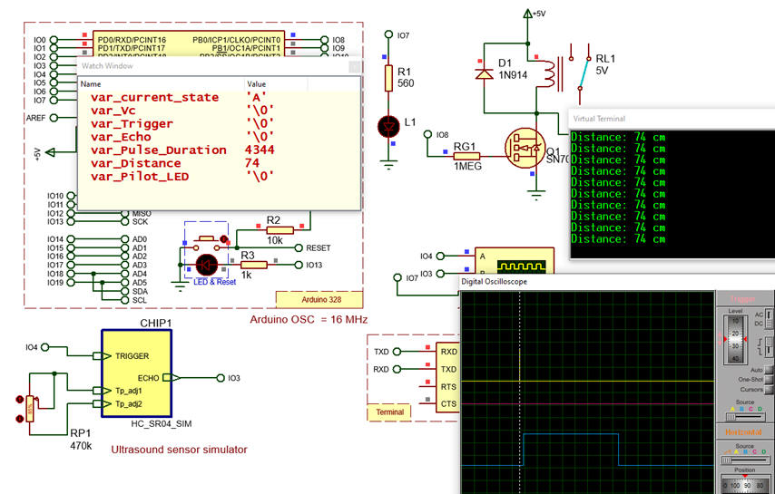
This Tap_control.zip is an example circuit capture in Proteus and the proposed software translating the truth tables and the datapath flowcharts.
 |
|
Fig. 10. Running the application and debugging |
5. Prototyping
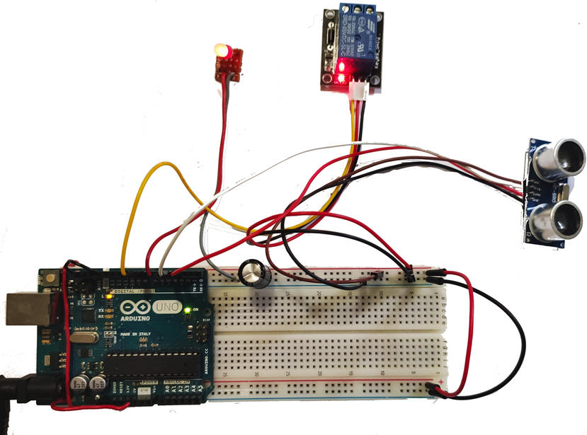
Once the system works in the simulator, the executable file can be uploaded to an Arduino board. Electro-valves, motors, or any other electrical appliances can be connected to the relay terminal block. It is time for characterising the application driving the ultrasonic sensor and finding bugs, if any, not observed in the simulator.
 |
|
Fig. 11. Prototupe using an Arduino UNO board. |
 |
|
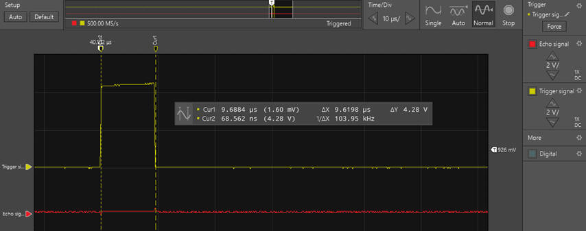
Fig. 12. Trigger signal measurement characterisation using the VB8012 compact instrument. |
 |
|
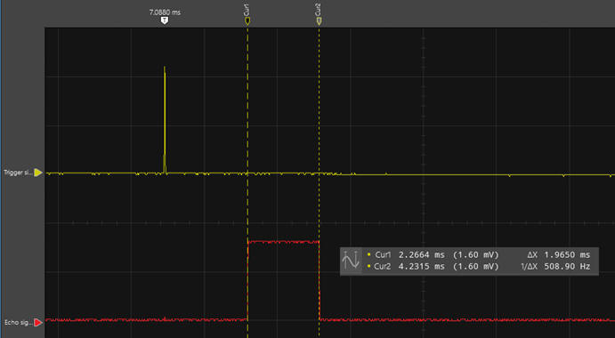
Fig. 13. Trigger and Echo pulse when no obstacle, but the ceiling at 2 m. |
 |
|
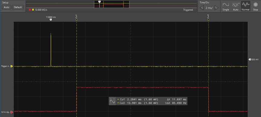
Fig. 14. Obstacle at 33.8 cm that switches ON the relay. |
A PCB Arduino shield can be designed using Ultiboard and Multisim and a plastic box can be manufactured using a 3D printer for screwing the application.
6. Report
Follow this rubrica> for writing reports.
| Home Term 26/27-Q1 Contact Products Electronic devices and companies Software Books Magazines Instruments DEE Library EETAC DEEL |

|
|
| Web activa des de 09/2001, @ F. J. Robert, Web editat amb Microsoft Expression Web 4. El contingut és un complement als materials d'estudi del curs Circuits i Sistemes Digitals disponibles al campus digital Atenea. Llicència:Reconeixement 4.0 Internacional de Creative Commons |