|
|
Bachelor's Degree in Telecommunications Systems and in Network Engineering |
|
|
|
|||
|
|
1-digit BCD adder with LCD (design phase #2) |
|
|
|
|
|||
1-digit BCD adder with LCD display
(Under revision)
1. Specifications
Implement the second design phase of the application Adder_BCD_1digit. The idea is to enhance the circuit replacing the 7-segment displays by an LCD display to show operands and results.
Entity name: Adder_BCD_1digit_LCD. Use the PIC18F4520 microcontroller chip.
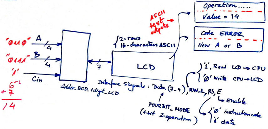 |
Fig 1. Symbol of the device to be designed. |
2. Planning
Ideas and discussion.
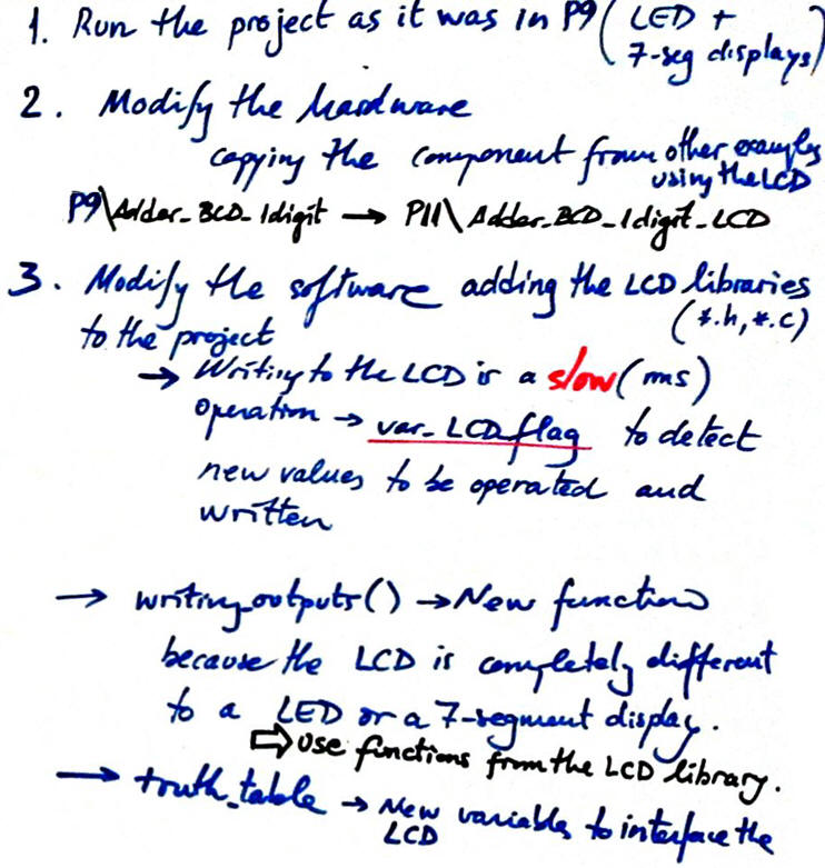 |
Fig. 2. Planning ideas. |
A) Planning hardware
A good idea is to connect inputs and outputs in free pins of PICDEM2 Plus prototyping board. In such board LCD display is connected to microcontroller's PORTD.
 |
|
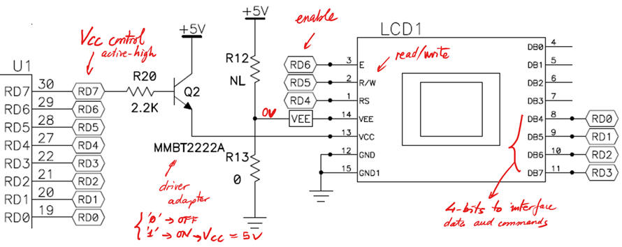
Fig. 3. Connecting 7 wires for the LCD interface and another one (RD7) for switching ON/OFF its power supply. |
A) Planning software
Software modifications indicated in the main loop.
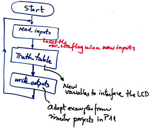 |
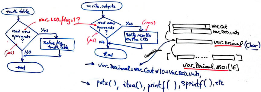
Fig. 4. Software modifications. |
Represent the RAM variables required in this application. What is var_LCD_flag? Why we need such indicator?
 |
Fig. 5. New RAM variables. |
|
|
|
Fig. 6. Hardware-software diagram. |
Explain the new ideas in init_system(). Where the LCD is configured?
Explain how the flowchart of read_inputs() is modified.
Explain how the flowchart of write_outputs() is modified.
 |
|
Fig. 7. Activate var_LCD_flag when new operands are polled. |
Organise a MPLABX - XC8 IDE project targetting a PIC18F4520 at location:
C:/CSD/P11/Adder_BCD_1digit_LCD/(files)
3. Development - 4. Testing interactively
A) Developing hardware
Proteus hardware circuit Adder_BCD_1digit_LCD.pdsprj.
|
Fig. 8. Circuit captured in Proteus. |
B) Developing software
C source code Adder_BCD_1digit_LCD.c.
|
Fig. 9. Using LCD functions for writing ASCII messages. |
C) Step-by-step testing
Run the Proteus simulator. Do it in step by step mode while watching variables and placing break points, specially for following var_LCD_flag.
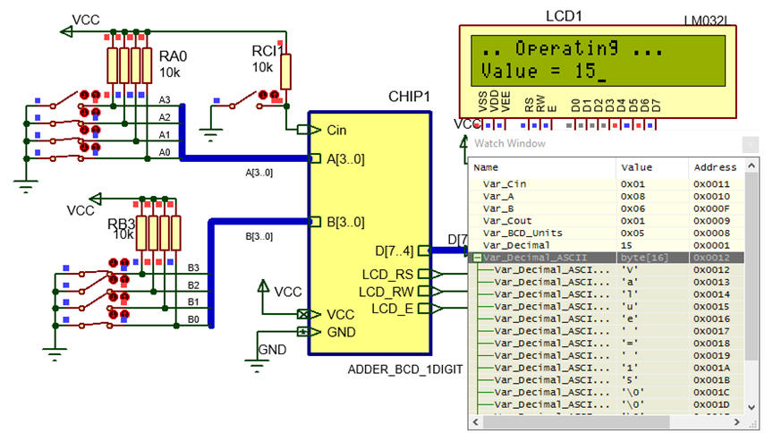 |
Fig. 10. The circuit in "run" mode while monitoring the variables in the "watch" window. |
|
NOTE: This is yet another version of the same project where dynamic data is ajusted to 2 bytes (plus the end of string code '\0' null terminator). It shows how to represent dynamic numerical data, in this case an int result (Var_Decimal) from an arithmetic operation to a char string (Var_Decimal_ASCII[16] or Var_Decimal_ASCII[3]) sized for LCD. Similar formatting (sprintf()) is required for representing double int or float variable types. |
5. Report
6. Prototyping
Use training boards such PICDEM2 or EXPLORER 8.
| Home Term 26/27-Q1 Contact Products Electronic devices and companies Software Books Magazines Instruments DEE Library EETAC DEEL |

|
|
| Web activa des de 09/2001, @ F. J. Robert, Web editat amb Microsoft Expression Web 4. El contingut és un complement als materials d'estudi del curs Circuits i Sistemes Digitals disponibles al campus digital Atenea. Llicència:Reconeixement 4.0 Internacional de Creative Commons |