|
|
Bachelor's Degree in Telecommunications Systems and in Network Engineering |
|
|
|
||
|
|
6-bit Johnson sequencer with ST/SP button (design phase #3) |
|
|
|
||
6-bit Johnson sequencer with TMR0 (phase #3) or TMR2 (phase#4)
(Under revision)
1. Specifications
Design phase #3: Invent the Johnson_sequencer_mod12_LCD_TMR represented in Fig. 1 enhancing project Johnson_sequencer_mod12_LCD phase #2 using TMR0 peripheral to replace the external CLK signal.
-
Let us running the sequencer by means of interrupts from internal timer peripheral TMR0.
-
The sequencer has to advance at a rate of 10 counts per second, thus the timer will generate an interrupt every 100 ms. This means that SQ_out has a period of 1.2 s (frequency of 8.33 Hz).
-
Add TMR_wave output to show on the oscilloscope the waveform generated by TMR0 toggling logic value every TMR interrupt (var_CLK_flag signal).
 |
Fig 1. Project Johnson_sequencer_mod12_LCD_TMR symbol and I/O signals (Visio). |
Phase #4: As a final improvement, replace TMR0 by TMR2 and compare solutions and discuss performance. Why TMR2 is better for precision timing applications?
2. Planning
A) Planning hardware
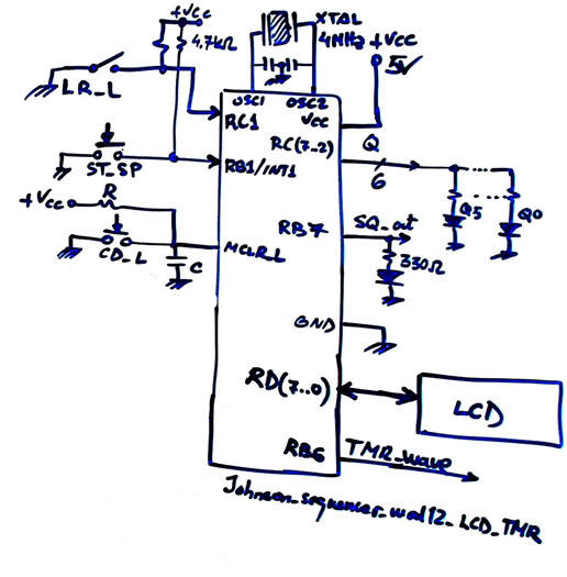
The circuit updated is represented in Fig. 2.
|
Fig 2. Circuit sketch. |
B) Planning software
We pretend to generate var_CLK_flag using internal TMR0. Therefore, the project has the same conception and only minor changes are necessary. In set_CLK_source state TMR0 will be selected and set as the source for sequence timing. In stop_CLK TMR will be switch off.
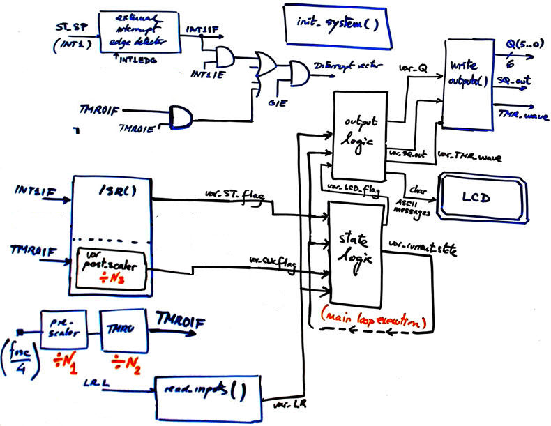
Fig. 3 shows how the hardware-software diagram is modified.
|
Fig 3. Software-hardware diagram when using TMR0. |
In this application TMR0 must be a timer derived from the internal FOSC/4 system time-base. Thus, T0CS = 0.
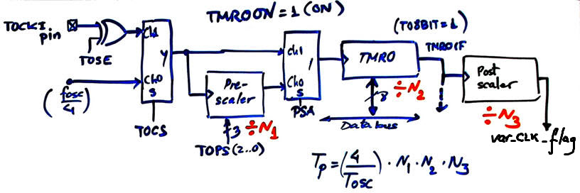 |
Fig 4. Functional structure and configuration bits in TMR0. |
To obtain a var_CLK_flag signal every TP = 100 ms, a convenient set of parameters may be: N1 = 32, N2 = 125, N3 = 25 (char variable). It means a hardware interrupt TMR0IF every 4 ms.
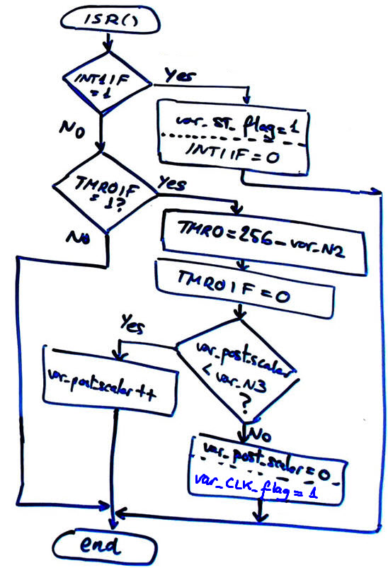 |
Fig 5. Algorithm in ISR() to generate var_TMR0_flag from TMR0 interrupts. |
Project location for design phase #3 is:
C:\CSD\P12\Johnson_seq_mod12_LCD_TMR0\(files)
Project location for design phase #4 is:
C:\CSD\P12\Johnson_seq_mod12_LCD_TMR2\(files)
3. Development and 4. Testing
A) Developing hardware
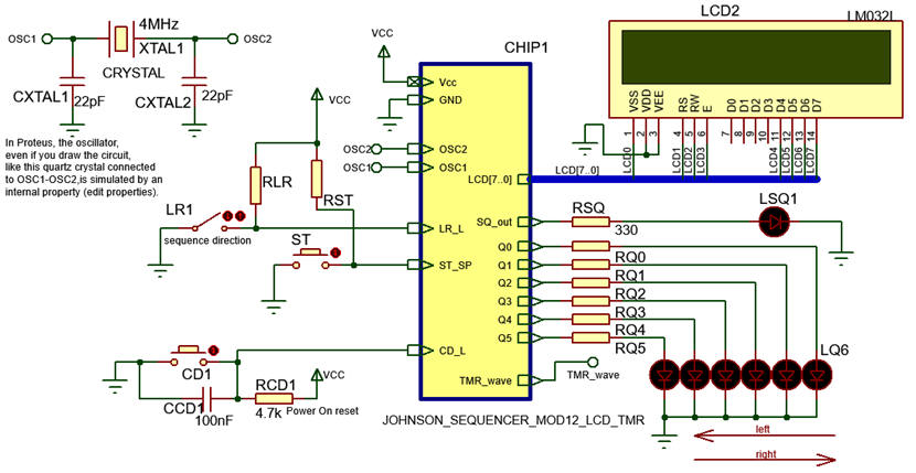
Circuit captured in Proteus is Johnson_sequencer_mod12_LCD_TMR.pdsprj.
 |
|
Fig. 5. Circuit captured in Proteus. External CLK is deleted and the functionality replaced by TMR0. |
B) Developing software
Source file Johnson_sequencer_mod12_LCD_TMR.c and LCD libraries must be compiled in the same MPLABX project for the target PIC18F4520 microcontroller.
C) Step-by-step testing
 |
|
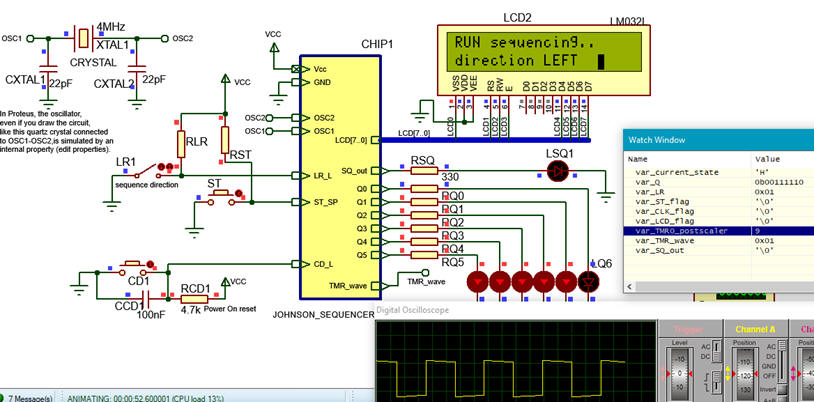
Fig. 6. Circuit running and watching variables and oscilloscope waveforms. |
Measure the period of the output TMR_wave.
Why using the calculated values the time elapsed between TMR0 interrupts is 104.52 us instead of 100 ms ?
What is the meaning of software overhead? How to solve it? Try to replace TMR0 by TMR2 and repeat measurements.
5. Report
Follow this rubric for writing reports.
6. Prototyping
Download the application to a training board an verify that it works as expected and the same as in the simulator.
Annex
Optional. In the same way that we can use other similar libraries such as Timer XLCD extended libraries for controlling the LCD, it is also possible to find what eXtended libraries are required for commanding the TMR0 replacing low-level code in previous examples.
| Home Term 26/27-Q1 Contact Products Electronic devices and companies Software Books Magazines Instruments DEE Library EETAC DEEL |

|
|
| Web activa des de 09/2001, @ F. J. Robert, Web editat amb Microsoft Expression Web 4. El contingut és un complement als materials d'estudi del curs Circuits i Sistemes Digitals disponibles al campus digital Atenea. Llicència:Reconeixement 4.0 Internacional de Creative Commons |