|
|
Bachelor's Degree in Telecommunications Systems and in Network Engineering |
|
|
|
|||||
Chapter 2 problems |
- D2.10 - |
Vending machine |
|||
|
|
|||||
1. Specifications
Let us design a simple coffee vending machine connected to a coin acceptor as shown in Fig. 1.
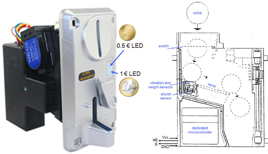
A coin sensor system for automatic vending machines is a dedicated processor containing sensors, switches, mechanical and electronic parts. From such commercial coin acceptor, we will imagine only two outputs HE and E generating CLK synchronised single digital pulses every time 0.5 �‚� and 1 �‚� coins are detected. Other coins and fake money are rejected. HE and E pulses can light LEDs and also can drive a FSM vending to service coffee.
 |
|
Fig. 1. Commercial coin acceptor and its simplifed symbol. |
The way the coin acceptor works may be simplified as represented in Fig. 2. Only inserted legal 0.5 �‚� and 1 �‚� coins generate half euro (HE) and euro (E) pulses.
 |
|
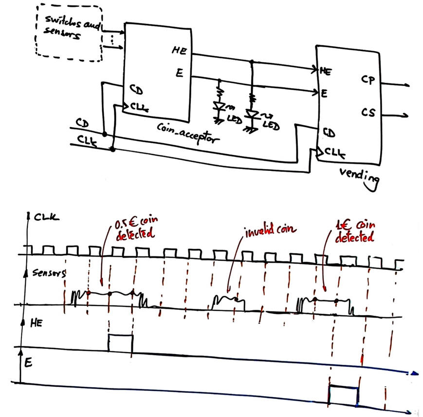
Fig. 2. Example of symbols and waveforms showing how signals from sensors, buttons and switches with the correponding microcontroller software can generate synchronous digital pulses to drive the vending unit. Let us assume that the CLK is 40 Hz. |
The vending machine will generate a coffee pulse (CP) to trigger the coffee dispenser once the amount of 1.5 �‚� is detected. A change signal (CS) pulse to return to the user a 0.5 �‚� coin will be generated when the machine accumulates 2 �‚�.
Some questions to kick off the project and organise it in four sections. Apply the FSM architecture to this problem.
a) Draw and discuss a timing diagram for the vending block.
b) Adapt the FSM architecture to this problem, naming and connecting all signals and inputs and outputs.
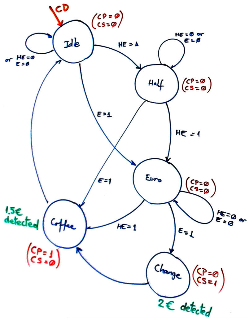
c) Infer and draw the circuit's state diagram. Annotate all the state transitions and outputs. For instance, study the diagram represented in Fig. 3.
 |
|
Fig. 4. The state diagram showns how coffee pulse output CP = '1' only when the state coffee dispensing is reached. In a similar way, change signal CS = '1' only when the state returning change is reached because 2 �‚� are accumulated and a 0.5 �‚� coin has to be released. |
d) Draw the state register if coding the machine in binary sequential. How many D_FF of memory are used in this problem?
e) Write the CC2 truth table to obtain the outputs of the circuit and its flowchart.
f) Design the CC1 truth table to obtain the next state to go and its flowchart.
g) Write the VHDL file and start an EDA project in Quartus Prime to synthesise the circuit vending and obtain results.
h) Inspect the RTL and verify that it looks like your initial FSM concept. Inspect the technology view and check the number of D_FF. Print and comment the schematics.
i) Write a VHDL test bench stimulating HE and E signals and run the EDA simulation tool to verify your vending design.
Optional. Other additional features:
j) If the user spend more than 1 minute to input all the coins, the machine goes back to idle automatically. Invent the CLK_generator and the timer block to implement such feature.
| Home Term 23/24-Q2 Contact Products Electronic devices and companies Software Books Magazines Instruments DEE Library EETAC DEEL |

|
|
| Web activa des de 09/2001, @ F. J. Robert, J. Jordana. Web editat amb Microsoft Expression Web 4. El contingut és un complement als materials d'estudi del curs Circuits i Sistemes Digitals disponibles al campus digital Atenea. Llicència:Reconeixement 4.0 Internacional de Creative Commons |