|
|
Bachelor's Degree in Telecommunications Systems and in Network Engineering |
|
|
|
Timer 18.5 s. Design phase #4: TMR2 time-base |
Dedicated processor (FSM + datapath), peripherals LCD and TMR2
Design phases ==> #1: Timer ==> #2: Timer_LCD ==> #3: Timer_LCD_TMR0 ==> #4: Timer_LCD_TMR2
| 1. Specifications | Planning | Dev. & test | Prototype | report |
Design phase #4: Modify the previous Timer_LCD_TMR0 in design phase #3 so that the time-base is generated by TMR2. Fixed-time timer, for instance TP = 18.5 s. Let us consider the FOSC = 8 MHz crystal oscillator running the PIC18F46K22 µC on the CSD_PICstick board for prototyping.
 |
|
| Fig. 1. Project entity is the same in phase #3 replacing the internal peripheral TMR0 by TMR2. The quartz crystal that is used for running the µC will also determine time accuracy for this application. |
|
Common features:
- The same inherited features design phase #3 project.
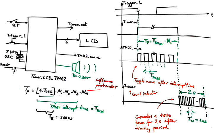
- TMR2 peripheral to generate from the TB = 500 ns a square output signal TMR2_wave with a period 2·TTMR2. (the waveform will toggle every TMR2 interrupt time).
- Implement the circuit in the CSD_PICstick as a prototype and perform measurements to characterise the circuit's performance.
- Optional: Add a buzzer that will sound for 2 s at 1 kHz tone once the timing period has ended.
Common features:
- The same features as in project design phase #1 Timer, phase #2 Timer_LCD, and phase #3 Timer_LCD_TMR0 all of them proposed as the tutorial to be discussed in Lab11.
- TMR2 peripheral to generate 4 ms time-base replacing TMR0.
- Optional: Add a buzzer that will sound for 2 s at 1 kHz once the timing period has ended.
| Specifications | 2. Planning | Dev. & test | Prototype | report |
A) Planning hardware
The same circuit from design phase #3 replacing the TMR0 circuit by the new TMR2 that has a few variations: hardware reset on overflow, 8-bit wide, and includes a postscaler.
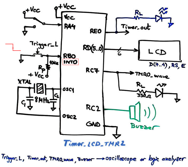 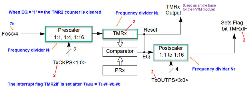 |
Fig. 2. Hardware schematic for the top timer application and also the TMR2 peripheral hardware to configure. |
Study how the TMR2 works, its configuration bits and interrupt mechanism. How to design its functionality using VHDL?
 |
Fig. 3. The TMR2 proposed as a Chapter 2 application. |
How to add a software postscaler variable to generate long counts?
B) Planning software
It is the same design presented in phase #3 but replacing TMR0 by TMR2. The design equation for generation timing periods TP is slightly modified by the new postscaler circuit.
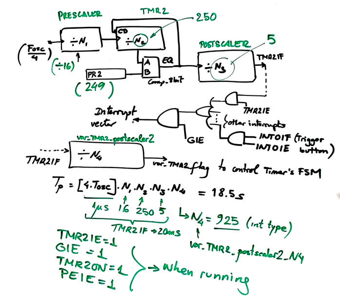 |
Fig. 4. Parameters for adjusting TMR2. We will generate TMR2 interrupts every TTMR2 = 4 ms. |
Project location:
C:\CSD\P12\Timer_LCD_TMR2\(files)
| Specifications | Planning | 3. Dev. & 4. test | Prototype | report |
We will start copying the previous files from design phase #1 in the new folder location changing their names. We will compile and run the simulations to check that everything works before adding the LCD code introducing and changing their names.
A) Developing hardware
This is an example electronic circuit "Timer_LCD_TMR2.pdsprj". It is the same as in design phase #3 because we are simply replacing internal peripherals TMR0 by TMR2.
B) Developing software
The LCD kit software driver, these LCD library files "lcd.c", "lcd.h" , presented in P11, have to be included in the project. The file "config.h" contains all the microcontroller configuration bits. This is the example software source code "Timer_LCD_TMR2.c". Generate the executable (*.hex) and debugging file (*.cof) for Proteus simulations.
C) Step-by-step testing
The circuit running is captured in Fig. 5.
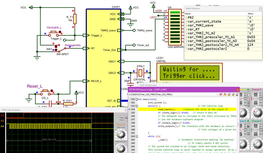 |
Fig. 5. Proteus capture that shows how to debug using the watch window and step by step mode. |
| Specifications | Planning | Dev. & Test | 5. Prototype | Report |
Use the CSD_PICstick to verify your design as we did in LAB11 for testing the TMR0.
|
|
Fig. 6. Prototype running. |
Add the buzzer to sound the alarm when the timing period has finished. What king of modifications are required?
Once you are introduced to microcontroller basics by means of these CSD tutorial projects in bare-metal, you can go ahead replicating them switching to the professional environment: Microchip Code Configurator MCC Melody. It manages efficiently all the the microcontroller hardware.
| Specifications | Planning | Dev. & Test | Prototype | 6. Report |
Follow this rubric for writing reports.
| Home Term 26/27-Q1 Contact Products Electronic devices and companies Software Books Magazines Instruments DEE Library EETAC DEEL |

|
|
| Web activa des de 09/2001, @ F. J. Robert, Web editat amb Microsoft Expression Web 4. El contingut és un complement als materials d'estudi del curs Circuits i Sistemes Digitals disponibles al campus digital Atenea. Llicència:Reconeixement 4.0 Internacional de Creative Commons |