|
|
Bachelor's Degree in Telecommunications Systems and in Network Engineering |
|
|
|
|||||
Chapter 2 problems |
- D2.3 - |
LED rotator (FPGA-VHDL) |
|||
|
|
|||||
1. Specifications
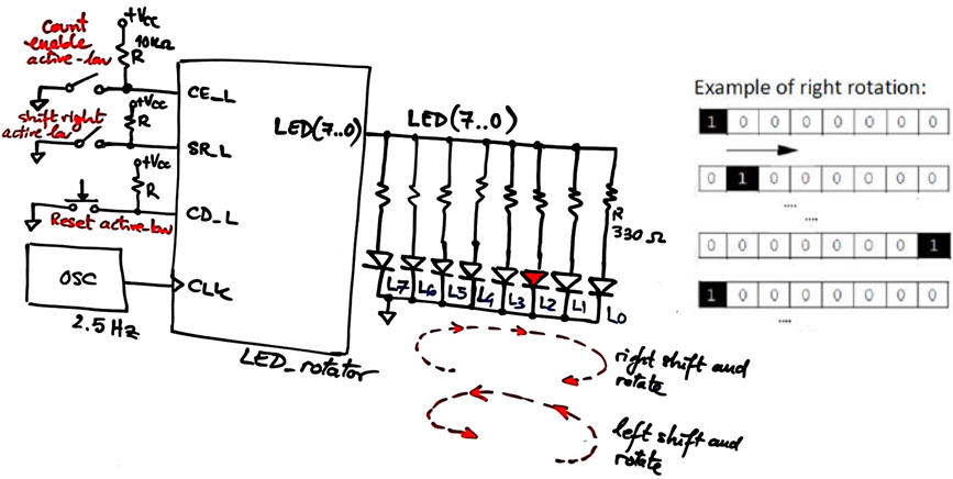
Our aim is to implement a LED rotator like the one represented in Fig. 1, which is basically a FSM acting as an 8-bit one-hot shift register that runs continuously. The same project designed programming a μC is in D3.3.
The system operates by means of two control signals:
CE_ L = 1 (do nothing), CE_ L = 0 (run rotating)
SR_L = 0 (shift and rotate right), SR_L = 1 (shift and rotate left)
 |
|
Fig. 1. LED rotator. |
Some questions to kick off the project and organise it in four phases:
a) Draw the function table and the state diagram indicating state transitions and outputs.
b) Apply the FSM architecture to this problem and draw the state register based on D_FF. Deduce how many D_FF are required if coding states in Gray.
c) Write the truth table of CC1 and CC2 and their equivalent behavioural interpretations using flowcharts.
d) Write the FSM VHDL file and develop the circuit for a MAX II target chip using EDA tools. Inspect the RTL and technology views. How many D_FF registers are used in this application?
e) In Fig. 1 the circuit works at 2.5 Hz, but what is the maximun speed of operation if the target chip is an Intel MAX II?
Ideas on the solution are discussed in 1920Q1 EXA2 (P4)
| Home Term 24/25-Q1 Contact Products Electronic devices and companies Software Books Magazines Instruments DEE Library EETAC DEEL |

|
|
| Web activa des de 09/2001, @ F. J. Robert, J. Jordana. Web editat amb Microsoft Expression Web 4. El contingut és un complement als materials d'estudi del curs Circuits i Sistemes Digitals disponibles al campus digital Atenea. Llicència:Reconeixement 4.0 Internacional de Creative Commons |