|
|
Bachelor's Degree in Telecommunications Systems and in Network Engineering |
|
| | ||
PLA7: Designing large counters, registers, dedicated processors |
||
| NOTE: This post lab assignment must be solved only after having completed successfully lab session Lab7 because you will copy and adapt ideas and materials from it. |
This group submission at Atenea includes the report in a PDF file, the zipped project, a 10 min. max video presentation and also your self-assessment.
NOTE: ===> To prepare your video presentation, consider the assessement and feedback you got from PLA3
Specifications
Continue your PLA6 design phase #1 solving project sections 3 - 4 - 5.
Solve your PLA6 design phase #2.
| Example of individual/group assignments | ||||
| Project number | Circuit entity | FSM encoding | Target chip | |
| Est./group 1 | D2.5 | LED lamp dimmer | one-hot | Cyclone IV |
| Est./group 2 | D2.6 | 7-segment sequencer | binary radix-2 | MAX II |
| Est./group 3 | D2.23 | Earbuds control buttons | Gray | MAX II |
| Est./group 4 | D2.5 | LED lamp dimmer | binary radix-2 | Cyclone IV |
| Est./group 5 | ... | ... | ... | ... |
NOTE: You can choose whether to solve PLA7 individually or in cooperative group. Discuss it with your instructor.
Follow this rubric for writing reports.
Invest in this project the corresponding study time, no more. This PLA7 is a kind of introduction to capstone projects for completing our chapters on VHDL design. It is not that important to complete all the project design phases than paying careful attention on specifications, finding similar commercial products, planning design phases, imagining the correct control signals and output devices, selecting and interconnecting components and propose feasible architectures. At this point you already have got enough experience to develop and test these applications if they are well planned. Therefore, focus your group discussion in producing a quality planning based on CSD standard components and procedures.
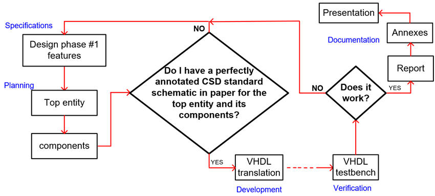
Repeat this project flowchart for the several design phases:
Time is a valuable finite resource. Learn to manage and maximise your study time: if after having studied in detail our materials, you do not find a component of your interest, ask questions on how to locate or adapt it from digsys lectures and projects and labs tutorials.
P_Ch2 marking grid for pprojects PLA6 and PLA7
P_Ch2 => 6% of your final grade => PLA6 (50%) + PLA7 (report + video, 50%)
| Work assessments to be carried out in laboratory sessions | |||
| PLA6 | |||
| 5p | |||
Note Work in progress includes completing tutorials, sample reports, sketches, diagrams, discussions, Q & A, presentations, live demonstrations, results, measurements, etc.
| PLA7 handwritten report and video presentation: | ||||
| Video | Report | |||
| 2p | 3p | |||
Notes on lab assessment: student grades are not simply reflecting report or video quality, but implicitly, they include laboratory participation, questions and answers, problem solving skills, attendance and punctuality, active attitude and group work.
Reflect and give us your group feedback on what you learned in chapter 2 (from P5 to P8). Add a short paragraph in the final section of your PLA7 discussing aspects that you consider positive and negative.
| Home Term 24/25-Q1 Contact Products Electronic devices and companies Software Books Magazines Instruments DEE Library EETAC DEEL |

|
|
| Web activa des de 09/2001, @ F. J. Robert, J. Jordana. Web editat amb Microsoft Expression Web 4. El contingut és un complement als materials d'estudi del curs Circuits i Sistemes Digitals disponibles al campus digital Atenea. Llicència:Reconeixement 4.0 Internacional de Creative Commons |