|
|
Bachelor's Degree in Telecommunications Systems and in Network Engineering |
|
|
|
|||||
Chapter 2 problems |
- D2.22 - |
Bit pattern generator |
|||
|
|
|||||
1. Specifications
Design a bit pattern generator as shown in Fig. 1. The key component is a datapath consisting of a 12-bit right shift register. Single event (shifter) or periodic sequences (rotator) up to 12-bit can be configured using input control signal M. After the initial CD signal, the 12-bit pattern is loaded in parallel. Up to four bit rates are configured using CF vector. CLK signals are derived from an external 50 MHz oscillator and it is also available as an output
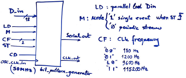 |
| Fig. 1. Symbol and main features for configuring bit sequences. |
Some example patterns are represented in Fig. 2.
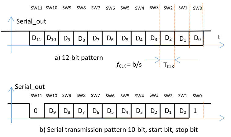 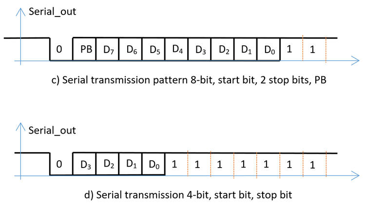 |
| Fig. 2. bit pattern examples. |
A circuit upgrade (design phase #2) can be conceived using a RAM chip to store and generate larger 12-bit patterns.
a) Discuss the given specifications. Find laboratory instruments of this kind. Find applications for such bit generator. How to characterise digital transmissions using eye diagrams, pattern generators and oscilloscopes? Some references: 1, 2, 3.
Planning
b) Plan an internal architecture for our bit_pattern_generator circuit conceiving a dedicated processor as studied in P8.
c) Organise the circuit datapath.
d) Infer a state diagram for the FSM.
e) Plan the CLK_Generator circuit and how to select CLK_out.
Development
f) Translate all components into VHDL and asseemble the top entity.
g) Select the Intel Cyclone IV EP4CE115F29C7 populating the DE2-115 board from Terasic and synthesise your circuit.
h) Analyse TRL and technology schematics. Check the number of D_FF used in this design.
Test
i) Generate from Quartus Prime the testbench fixture skeleton. Rename it and move it to the project folder.
j) Start and run a functional simulation project using ModelSim to verify that the device operates as expected.
k) Run a gate-level timing simulation to measure the maximum speed of operation.
Prototyping
l) Organise a bit_pattern_generator_top circut to condition switches, buttons, LED and outputs.
m) Assign pins and verify using laboratory instrumentations that the circuit works as expected.
| Home Term 23/24-Q2 Contact Products Electronic devices and companies Software Books Magazines Instruments DEE Library EETAC DEEL |

|
|
| Web activa des de 09/2001, @ F. J. Robert, J. Jordana. Web editat amb Microsoft Expression Web 4. El contingut és un complement als materials d'estudi del curs Circuits i Sistemes Digitals disponibles al campus digital Atenea. Llicència:Reconeixement 4.0 Internacional de Creative Commons |