|
|
Bachelor's Degree in Telecommunications Systems and in Network Engineering |
|
|
|
|||||
Chapter 1 problems |
- D1.5 - |
8-bit subtractor using Subtractor_1bit |
|||
|
|
|||||
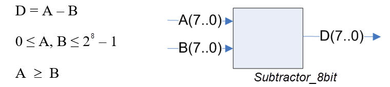
1. Specifications
We want to implement a circuit for subtracting 8-bit binary radix-2 numbers as represented in Fig. 1.
The same project B3.5 is proposed in Chapter 3 for learning the basics of μC software organisation and basic digital I/O.
|
|
Fig. 1. The entity of a Subtractor_8bit and the operands range. |
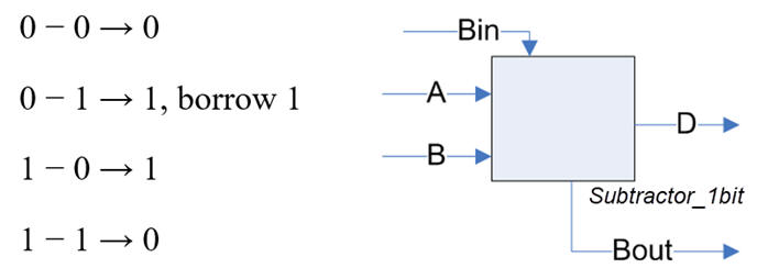
The strategy is to use plan C2, chaining 1-bit subtractors instead of the standard way based on 1-bit adders and two's complement convention discussed in P4. Thus, the circuit will work only with radix-2 numbers. Fig. 2 shows the building block Substractor_1bit.
|
|
Fig. 2. The entity of a Subtractor_1bit and its truth table. |
So, we can chain many Subtractors_1bit by connecting the "borrows" in the same way we connect the "carry" when adding:
|
|
Fig. 3. Algorithm for a chained 8-bit subtraction. |
Some questions:
- Try at least three operations:
A = 230, B = 45; A = 187, B = 177; A = 177, B = 187
- Draw a sketch of a timing diagram.
2. Planning
Conceiving the Subtractor_1bit component:
Option plan A: Implement the Subtractor_1bit using only NAND2 gates.
Some notes on its solution.
Option plan B: Write the code for the Subtractor_1bit in VHDL using a behavioural approach.
Conceiving the Subtractor_8bit:
Plan C2:
Draw the schematic of the 8-bit ripple subtractor (Subtractor_8bit) and describe it in VHDL, using components.
Implement the logic circuit of a pair of flags or indicators to detect special events like:
- A zero result D = A - B = 0
- A negative number D < 0 (A<B)
Develop the circuit targeting an Intel FPGA MAX II and inspect the RTL and the technology view.
Test your circuit writing a VHDL simulation testbench from the timing diagram in the specifications.
| Home Term 24/25-Q1 Contact Products Electronic devices and companies Software Books Magazines Instruments DEE Library EETAC DEEL |

|
|
| Web activa des de 09/2001, @ F. J. Robert, J. Jordana. Web editat amb Microsoft Expression Web 4. El contingut és un complement als materials d'estudi del curs Circuits i Sistemes Digitals disponibles al campus digital Atenea. Llicència:Reconeixement 4.0 Internacional de Creative Commons |