|
|
Bachelor's Degree in Telecommunications Systems and in Network Engineering |
|
|
|
|||||
Chapter 3 problems |
- D3.14 - |
Traffic light controller |
D3.13 |
D3.15 |
|
|
|
|||||
1. Specifications
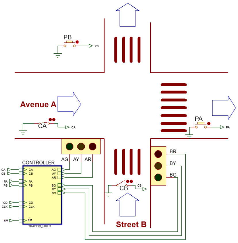
This project is an alternative version of the D2.14. Design a traffic light controller for the given street intersection in Fig. 1. Let us organise the project in several phases to make it easy to design and conceive.
 |
|
Fig 1. Street intersection to be controlled by our traffic_light system. |
Find information in internet on the green/yellow/red traffic light sequence used currently in Europe. Or simply observe a real traffic light operating and deduce its operative sequence.
Implement the basic traffic light sequence including only the button NM (night mode). This signal may come from a light sensor or an auxiliary clock. When NM = 0, day time, the normal traffic light sequence is generated. When NM = 1, night, both light poles are displaying intermitent yellow lights and thus the vertical pole signs are in use on the street intersection.
Draw an example of timing diagram (for example considering only the control signal in the design phase #1 bellow)
You can start imagining that here is a new colour pattern every CLK period.
Project location:
C:/CSD/P10/Traffic_light/files)
As a secon step, add car sensors CA and CB to stop the normal traffic light sequence operation when cars are not detected in a given street. The idea is that if no cars are detected in street B, there is no need to stop the cars in avenue A, they can circulate always in GREEN.
A) Planning hardware
Copy and adapt a circuit from a convenient tutorial project and name it Traffic_light.pdsprj. Assign pins to inputs and outputs accordingly to one of the following options (your instructior will tell you which):
Pin assignment option #1:
AG --> RB7; AY --> RB3; AR --> RA2
BG --> RC2; BY --> RC1; BR --> RA3
AC --> RB6; BC --> RB5
AP --> RA1; BP --> RC6
CLK --> RB2
NM --> RC5
Pin assignment option #2:
AG --> RB6; AY --> RB2; AR --> RA0
BG --> RC4; BY --> RC2; BR --> RA2
AC --> RB7; BC --> RB3
AP --> RA1; BP --> RC3
CLK --> RB1
NM --> RC7
Pin assignment option #3:
AG --> RB3; AY --> RB1; AR --> RA3
BG --> RC7; BY --> RC6; BR --> RA1
AC --> RB6; BC --> RB7
AP --> RC2; BP --> RA2
CLK --> RB0
NM --> RC2
Draw the hardware schematic. Buttons and switches, resistors, inputs, outputs, reset circuit MCLR_L and quartz crystal oscillator of 8 MHz. Explain how to configure inputs and outputs in init_system().
B) Planning software
Draw the flowchart of the general program organisation.
Draw and explain the hardware-software diagram. Explain the difference between variables and flag variables.
Infer the state diagram governing the machine.
Explain how to poll (read) the NM sensor and the other sensors (car and pedestrian) in read_inputs() using bitwise operations. Explain how to measure how many times per second these switches are read.
Explain how to drive output pins in write_outputs().
Explain the external interrupt mechanism for connecting the CLK that is governing the FSM. Explain how the ISR() is used.
Draw the state_logic() truth table and its equivalent flowchart ready for translation to C language.
Draw the output_logic() truth table and its equivalent flowchart ready for translation to C language.
Developing & testing (debugging)
Develop and test (debugging) the project capturing the hardware circuit in Proteus and writting the C source code.
| Note: Step-by-step tactical approach for developing and testing the project: Read one input at a time and run to check that the voltage value is correctly captured as a valid digital value in RAM memory. Write one output at a time and run to check that your code is correct to light the LED connected at the output pin. |
Design phase #2: an LCD will indicate ASCII messages and numbers.
Explain how to connect and program the LCD display to show ASCII messages such: "Street B GREEN", "Night operation", etc. on the screen.
Display a number indicating the downcount of the time left before RED in stret B and avelue A. .
Design phase #3: using internal peripheral TMR2. Real-time.
Configure and program TMR2 to replace the external CLK oscillator. Explain whether new states are required.
Add a sound wave for visually impaired people when the traffic light is GREEN.
Optional: Add PA and PB push-buttons to allow pedestrians to cross the intersection at any time when the traffic light sequence is locked in a given street because there are no cars in the other.
Optional: Other additional features:
Add a transmission system able to report the current state of the traffic light controller to a remote computer and to accept orders from a central system (full duplex communication).
Add a car speed measurement system with speed limit indicators and numeric displays signs.
| Home Term 23/24-Q2 Contact Products Electronic devices and companies Software Books Magazines Instruments DEE Library EETAC DEEL |

|
|
| Web activa des de 09/2001, @ F. J. Robert, J. Jordana. Web editat amb Microsoft Expression Web 4. El contingut és un complement als materials d'estudi del curs Circuits i Sistemes Digitals disponibles al campus digital Atenea. Llicència:Reconeixement 4.0 Internacional de Creative Commons |