|
|
Bachelor's Degree in Telecommunications Systems and in Network Engineering |
|
|
6-bit Johnson sequencer with ST/SP button (design phase #1) |
FSM, external interrupts INT0, INT1, state enumeration (plan X)
1. Specifications
(update this design) Implement a 6-bit Johnson sequencer (Johnson_mod12) using a PIC18F46K22 microcontroller chip. Software is organised mimicking a FSM and interrupt-driven to attend edge-triggered inputs such start/stop pushbutton (ST_SP) and CLK.
 |
Fig 1. Symbol of the device to be designed. External interrupts are used to detect counter's CLK edges and ST_SP button trigger signals (visio).
|
Features:
- Start/stop (ST_SP) pushbutton to trigger the operation and to stop it once the sequence has ended. The circuit is sensitive to the falling edge of this signal.
- 6-bit reversible Johnson counter sequence. LR_L = '1', left sequence; LR_L = '0', right sequence.
- The counter advances synchronously on the falling edge of an external CLK input of 10 Hz.
- SQ_out is a squared signal that is kept high for half consecutives states (fSQ_out = FCLK/MOD).
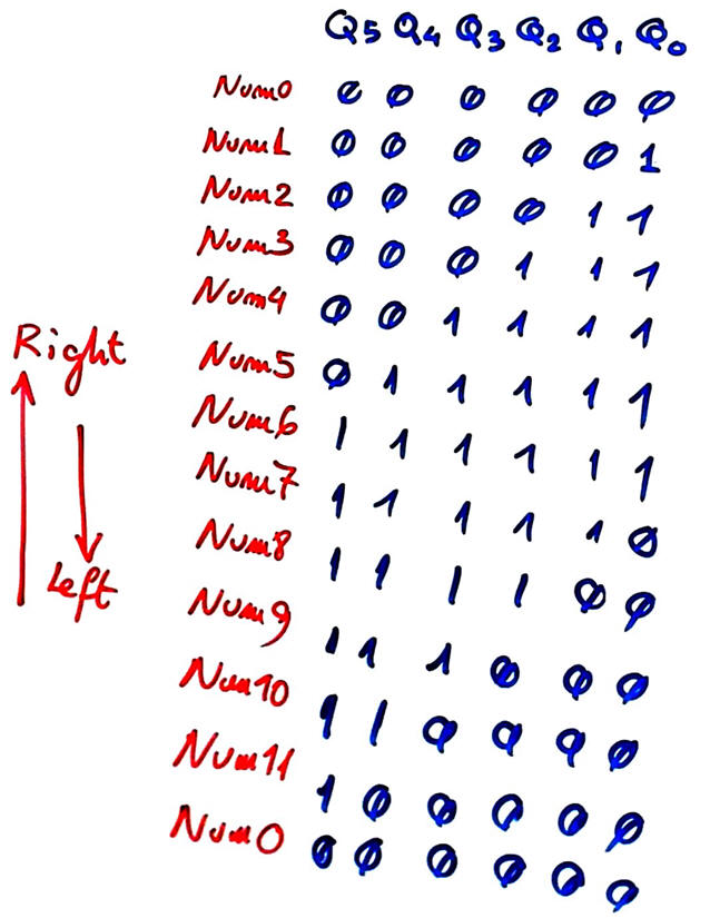 |
Fig 2. Johnson code. |
Well, as you see, it looks that simply once again we are revisiting the same circuits from Chapter 2. However, it is not only so, because in the end, comprehending correctly the basic behaviour of such simple systems will give you a great advantage when considering larger and far more complex systems. This P10 is the key to open the door of professional embedded microcontroller applications (data logging, signal acquisition and distribution, motors, LED lamps control, robotics, etc.).
2. Planning
A) Planning hardware
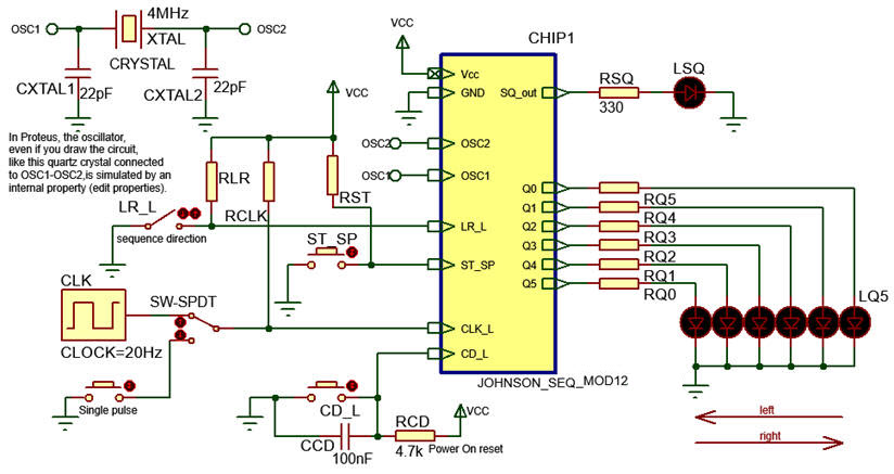
The proposed circuit is represented in Fig. 3. Some pins must be selected to be inputs and outputs, and in this case, external interrupt INT1 is used to detect ST_SP active edge event (falling signal transition) to start sequencing Johnson code. External interrupt INT0 will detect active edge (falling) from the external CLK.
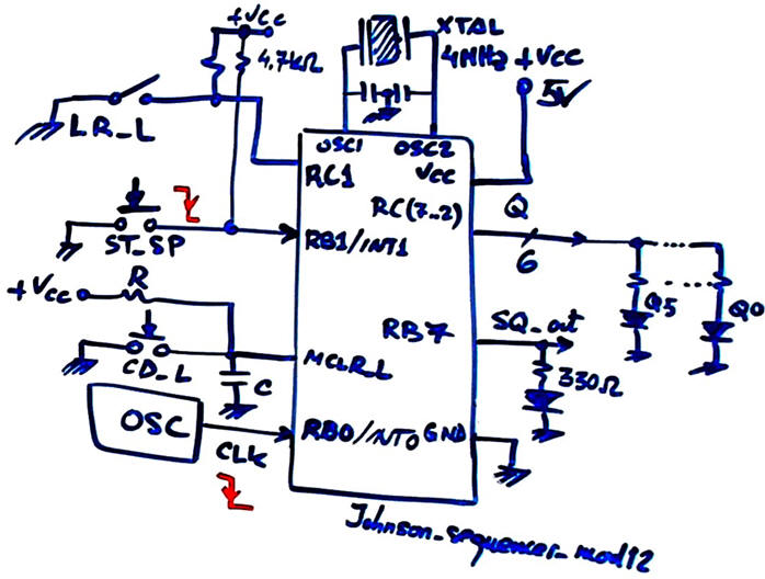 |
Fig. 3. Circuit. |
B) Planning software
We will organise the software as in P10 FSM adaptation. Draw the hardware-software diagram. The idea of implementing a "FSM in software" with some functions related to hardware (drivers) and the internal output and state logic software functions that process RAM variables.
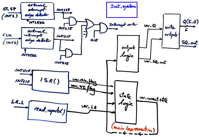 |
Fig. 4. Hardware-software diagram. |
Draw the state diagram. Timing sequence is only enabled when the machine has stated operating. While idle, only interruptions from ST_SP button are considered (represented in black), therefore, a pair od states for setting and stopping timing devices (this time an external CLK) are required before operations.
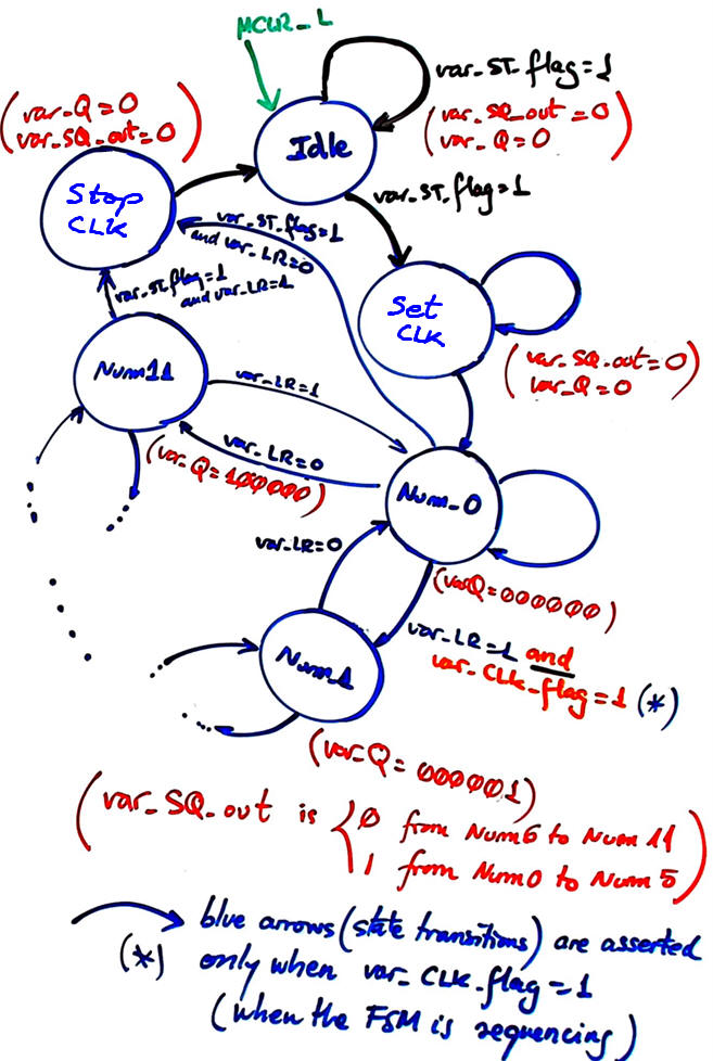 |
Fig. 5. State diagram proposal. |
Represent the RAM variables required in this application.
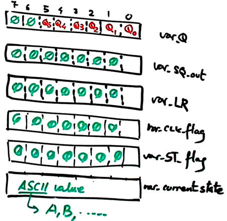 |
Fig. 6. RAM variables. |
Draw the main ideas of init_system(). Configure input and output pins. Consider as well interrupts configuration.
 |
Fig. 7. Data direction registers configuration. |
Draw the flowchart of read_inputs(). Basic function to poll input voltages as in P9.
Draw the flowchart of write_outputs(). Basic function to write pin voltages as in P9.
Infer how to organise the interrupt service routine ISR() to handle edge detections.
Draw state_logic() truth table
|
Fig. 8. State logic function (CC1). |
|
Fig. 9. State logic flowchart is a behavioural interpretation of the truth table. |
Draw output_logic() truth table.
|
Fig. 10. Output logic function (CC2). |
|
Fig. 11. Output logic flowchart is a behavioural interpretation of the truth table. |
Organise a MPLABX - XC8 IDE project targeting a PIC18F4520 at location:
C:/CSD/P10/Johnson_mod12/(files)
3. Development - 4. Testing interactively
A) Developing hardware
Draw the schematic of the application in Proteus "Johnson_mod12.pdsprj" (update) copying and adapting an example or tutorial.
 |
| Fig. 12. The sequencer captured in Proteus. (update) |
B) Developing software
Our planning ideas in previous section are translated to this C source file "Johnson_mod12.c" (update). Add the "config.h" header to your project. Do it section by section according to your plan, testing if it works before adding new code.
C) Step-by-step testing
Run the Proteus simulator. Do it in step by step mode while watching variables and placing break points, specially for following interrupt flags.
 |
|
Fig. 13. The circuit in "run" mode while monitoring the variables in the "watch" window. |
5. Report
Project report: sheets of paper, scanned figures, file listings, notes or any other resources. Follow this rubric for writing reports.
6. Prototyping
You're invited to download the application to a given training board an verify that it works as expected and the same as in the simulator.
| Home Term 26/27-Q1 Contact Products Electronic devices and companies Software Books Magazines Instruments DEE Library EETAC DEEL |

|
|
| Web activa des de 09/2001, @ F. J. Robert, Web editat amb Microsoft Expression Web 4. El contingut és un complement als materials d'estudi del curs Circuits i Sistemes Digitals disponibles al campus digital Atenea. Llicència:Reconeixement 4.0 Internacional de Creative Commons |