|
|
Bachelor's Degree in Telecommunications Systems and in Network Engineering |
|
|
|
|||||
Chapter 2 problems |
- D2.11 - |
Wireless IR TV remote control |
|||
|
|
|||||
1. Specifications
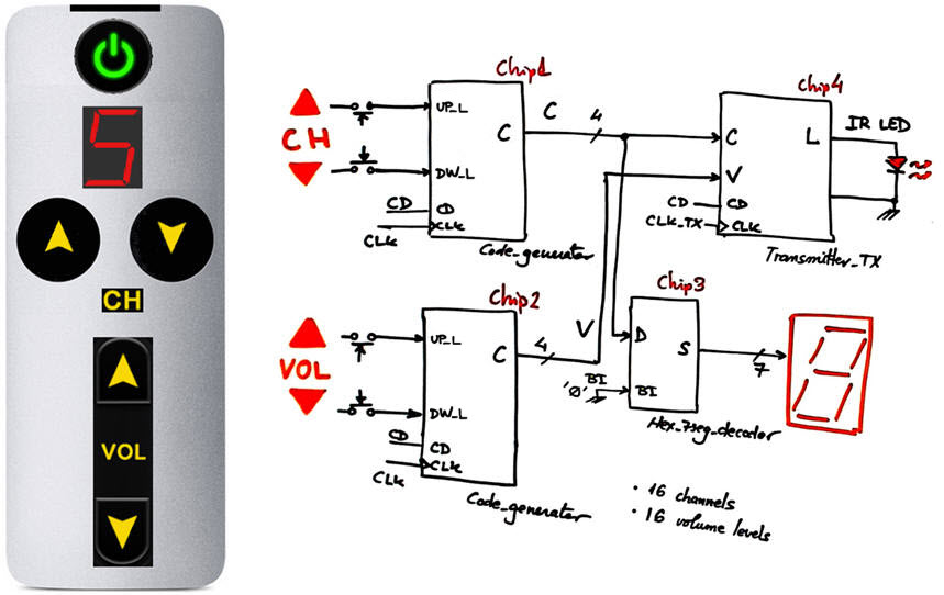
We want to design a simple TV remote as shown in Fig. 1. To simplify it, only channel and volume selection. Its internal architecture is based on channel and volume code generators of 4-bit binary combinations (chip1 and chip2), a Hex_7seg_decoder (Chip3), and the IR light series Transmitter_TX (Chip4). Chip3 was solved in Chapter 1 as a combinational circuit. Chip4 can be solved later in another design phase, thus we focus our attention in Code_generator. that is used twice.
 |
|
Fig. 1. Remote control and its suggested internal architecture. |
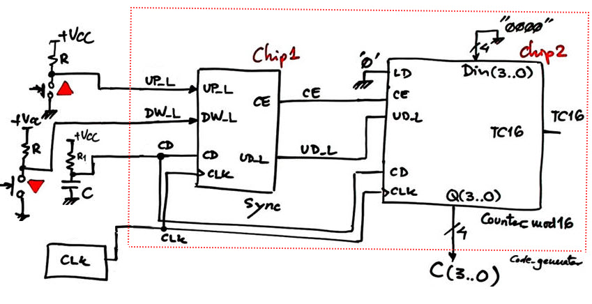
The idea of the chip Code_generator is represented in Fig. 2, a button synchroniser Sync Chip1 that drives a standard Counter_mod16 (Chip2) up and down when buttons UP_L (up) or DW_L (down) are pressed. In this design phase the output codes rotate when reaching the terminal count (15 when up and 0 when down).
 |
|
Fig. 2. Proposed architecture for the first design phase of the chip Code_generator. This a very simple dedicated processor where the datapath is a standard Counter_mod16 and the control unit is the Chip1 Sync. |
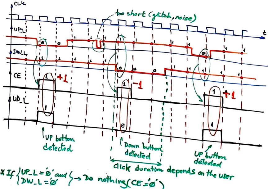
Timing signals are represented in Fig. 3. When the user clicks a button, output CE is set high during a CLK period; output UD_L is set high for a CLK period as well but only when the button UP is sensed. Clicking a button represents incrementing or decrementing the channel count by 1.
 |
|
Fig. 3. Example waveforms for the Sync Chip1 that show how control output signals CE and UD_L are generated depending on the buttons pressed. The key point is that one synchronous pulse is generated even if the button is kept clicked for a long time ('long time' here in this context means many CLK periods, which is the usual situation). |
Some questions to kick off the project and organise it in four sections. Apply the FSM architecture to this problem to solve the Sync circuit.
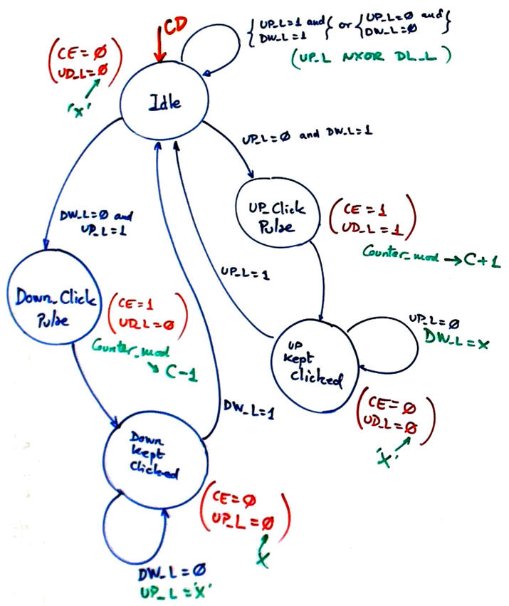
Infer and draw the Sync circuit state diagram. Annotate all the state transitions and outputs.
 |
|
Fig. 4. State diagram proposed for the Sync circuit to allow only one code generated after clicking a button. |
Adapt the FSM architecture to this problem, naming and connecting all signals and inputs and outputs.
Sketch a timing diagram showing the main operations.
Draw the state register if the FSM is coded in binary radix-2 (sequential). How many D_FF of memory are used in this problem?
Write the CC2 truth table to obtain the outputs of the circuit and its flowchart for a plan B description.
Design the CC1 truth table to obtain the next state to go and its flowchart for a plan B description.
Project location:
C:\CSD\P7\remote\(files)
Write the VHDL file and start an EDA project to synthesise the circuit and obtain results. Inspect the RTL and verify that it looks like your schematic. Check the number of D_FF, print and comment the schematics.
Get the Counter_mod16 VHDL code from its tutorial and build the complete top Code_generator project.
Write a VHDL test bench driving UP_L and DW_L signals and run the EDA simulation tool to verify your design.
The CLK frequency for this application to be able to sample buttons is 80 Hz. Design a CLK generator to obtain such frequency from a 50 MHz crystal oscillator.
How to design the Chip3 Transmitter_TX that has the function to convert 4-bit binary codes into IR light? Designing such block is a new interesting project where you can learn about frequency, pulse width or pulse duration modulations. You can even learn about the Receiver_RX block to convert light into 4-bit binary codes located in the TV set.
We can imagine that in a first step the transmitter will serialise the 8-bit parallel information [C(3..9) V(3..0)] (our serial transmitter and receiver circuits USART, Serial_transmitter), and in a second step will modulate the serial signal to drive an infrared (IR) LED. Initial references: 1, 2, 3, 4, 5, 6, 7, 8, 9, 10.
Design phase #2:
How to prevent rotation? When going up and the maximum code "1111" is obtained, do not rotate on the next click and go to zero, but keep the maximum code "1111". The same when going down, when the minimum code "0000" is obtained, do not rotate on the next click and go to the top combination "1111", but keep the minimum value if the user insist on clicking the down button.
Optional. Other additional features:
How to add a ON/OFF button to power up and switch off the TV set?
How can you implement this functionality: if you keep pressing the button the channel count goes up or down one number every second until the button is released (most commercial remotes work in this way). Thus, sequencing the 16 codes will be possible in two ways: clicking with short click the button 16 times or instead keeping the button pressed for 16 seconds.
| Home Term 23/24-Q2 Contact Products Electronic devices and companies Software Books Magazines Instruments DEE Library EETAC DEEL |

|
|
| Web activa des de 09/2001, @ F. J. Robert, J. Jordana. Web editat amb Microsoft Expression Web 4. El contingut és un complement als materials d'estudi del curs Circuits i Sistemes Digitals disponibles al campus digital Atenea. Llicència:Reconeixement 4.0 Internacional de Creative Commons |