|
|
Bachelor's Degree in Telecommunications Systems and in Network Engineering |
|
Design the interface for a portable CD player using a PIC18F4520 microcontroller as shown in Fig. 1.
The same project designed using hardware is stated in D2.1.
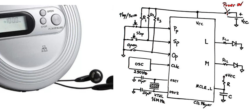 |
Fig. 1. CD player application and its symbol. Quartz crystal oscillator frequency is 8 MHz. |
Design phase #1: basic circuit.
Some questions to kick off the project and organise it as a FSM in four sections:
Draw an example of timing diagram.
Project location:
C:\CSD\P10\CD_player\(files)
A) Planning hardware
Copy and adapt a circuit from a convenient tutorial project and name it CD_Player.pdsprj. Assign pins to inputs and outputs accordingly to one of the following options (your instructor will tell you which):
Pin assignment option #1:
Pp --> RB1; Sp --> RB0; Op --> RC4
L --> RA2; M --> RB5
CLK --> RB2
Pin assignment option #2:
Pp --> RB2; Sp --> RB1; Op --> RB7
L --> RA3; M --> RC5
CLK --> RB0
Pin assignment option #3:
Pp --> RB0; Sp --> RB2; Op --> RB5
L --> RC2; M --> RA1
CLK --> RB1
Draw the hardware schematic. Buttons and switches, resistors, inputs, outputs, reset circuit MCLR_L and quartz crystal oscillator of 16 MHz. Explain how to configure inputs and outputs in init_system(). Open door switch is polled at the external CLK oscillator frequency of 250 Hz.
B) Planning software
Draw the flowchart of the general program organisation.
Draw and explain the hardware-software diagram. Explain the difference between variables and flag variables.
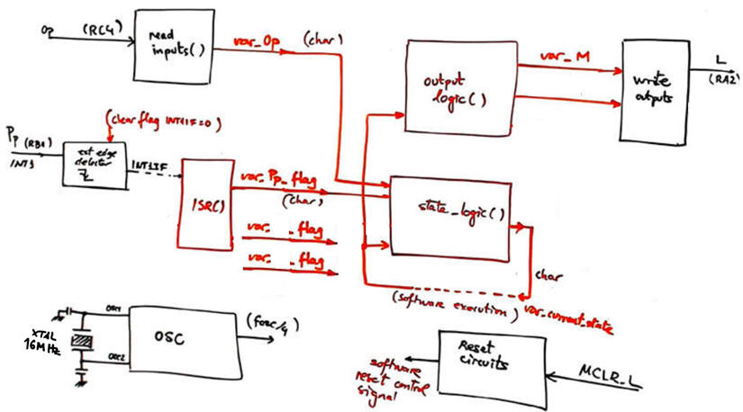 |
| Fig. 2. Example of a section of the hardware-software diagram sketch. |
Infer the state diagram governing the machine.
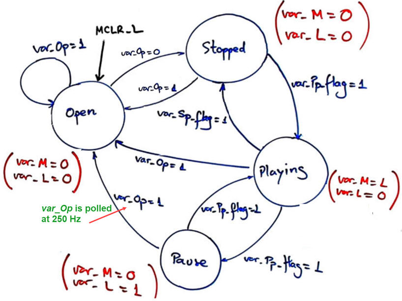 |
| Fig. 2. CD player FSM state diagram. |
Explain how to poll (read) the switch Open (Op) in read_inputs() using bitwise operations.
Explain how to drive output pins in write_outputs().
Explain the external interrupt mechanism for connecting the Play/pause button and the Stop button. Explain how the ISR() is used.
Draw the state_logic() truth table and its equivalent flowchart ready for translation to C language. What is the difference in the flowchart of polling continuosly the switch Open and polling it only when the external CLK is detected?
Draw the output_logic() truth table and its equivalent flowchart ready for translation to C language.
Developing & testing (debugging)
Develop and test (debugging) the project capturing the hardware circuit in Proteus and writting the C source code.
| Note: Step-by-step tactical approach for developing and testing the project: Read one input at a time and run to check that the voltage value is correctly captured as a valid digital value in RAM memory. Write one output at a time and run to check that your code is correct to light the LED connected at the output pin. |
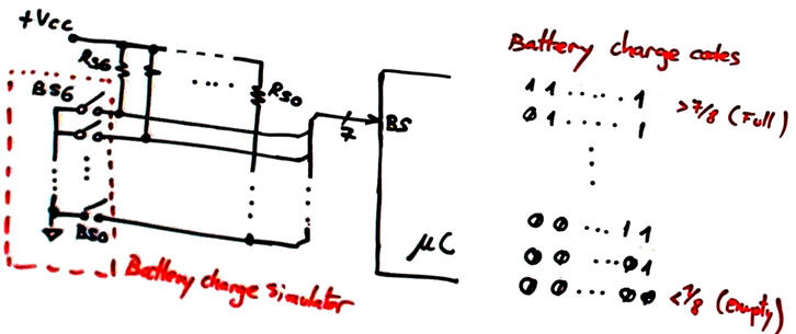
Design phase #2: an LCD will indicate ASCII messages and numbers. A sensor, simulated using switches and using 7-bit Johnson code is indicating as a numerical value the battery level in %.
Explain how to connect and program the LCD display to show ASCII messages on the screen such: "PLAY", "STOP", etc.
Connect the battery charge sensor and explain and compile the new LCD instructions and where they are located in the program flow. Visualise the battery level value as a percentage number.
Design phase #3: using internal peripheral TMR2
Configure and program TMR2 to generate a squared 2.5 Hz signal so the LED will be blinking intermittently when at Stopped state. Explain whether new states are required.
Optional: Measurig battery levels is a must for all portable electronic equipment. Battery voltage and charge sensors are acquired usually using analogue to digital converters. Find chips and schematics to monitor battery levels. Use one analogue channel of the embedded microcontroller A/D for this purpose to replace the digital charge simulator in this application.
| Home Term 24/25-Q1 Contact Products Electronic devices and companies Software Books Magazines Instruments DEE Library EETAC DEEL |

|
|
| Web activa des de 09/2001, @ F. J. Robert, J. Jordana. Web editat amb Microsoft Expression Web 4. El contingut és un complement als materials d'estudi del curs Circuits i Sistemes Digitals disponibles al campus digital Atenea. Llicència:Reconeixement 4.0 Internacional de Creative Commons |