|
|
Bachelor's Degree in Telecommunications Systems and in Network Engineering |
|
|
|
|||||
Chapter 2 problems |
- D2.17 - |
Down counter BCD modulo 24 (hours counter) |
|||
|
|
|||||
1. Specifications
Our goal is to design an hour counter to be used in a real-time clock device. Fig. 1 represents the symbol and function table.
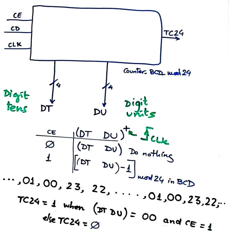 |
Fig 1. Symbol for the proposed entity. |
Let us use our plan C2 to build this Counter_BCD_mod24 chaining and truncating Counter_mod16 blocks.
CLK signal. Design a CLK generator to implement a 250 Hz squared waveform from a 50 MHz crystal oscillator.
Optional. Additional design phases for completing the tutorial project Hour_counter discussed in P7.
- Add an input UD_L to select up and down counting.
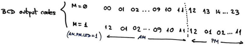
- Add an input M (mode) and an output PM_LED to allow representing output codes in 00 01 ··· 23 mode (when M = '0') and in 01 AM, 02 AM, ···, 11 AM, 12 PM, 01 PM, ··· mode when M = '1').
|
|
|||||
Chapter 2 problems |
Up counter BCD modulo 60 (seconds counter) |
||||
|
|
|||||
1. Specifications
Our goal is to design an minute or seconds counter to be used in a real-time clock device. Fig. 1 represents the symbol and function table. It is for counting using BCD code from 00 up to 59.
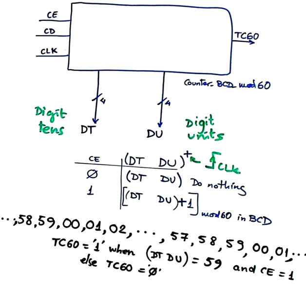 |
Fig 1. Symbol for the proposed entity. |
Let us use our plan C2 to build this Counter_BCD_mod60 chaining and truncating Counter_mod16 blocks.
CLK signal. Design a CLK generator to implement a 12.5 kHz squared waveform from a 50 MHz crystal oscillator.
| Home Term 23/24-Q2 Contact Products Electronic devices and companies Software Books Magazines Instruments DEE Library EETAC DEEL |

|
|
| Web activa des de 09/2001, @ F. J. Robert, J. Jordana. Web editat amb Microsoft Expression Web 4. El contingut és un complement als materials d'estudi del curs Circuits i Sistemes Digitals disponibles al campus digital Atenea. Llicència:Reconeixement 4.0 Internacional de Creative Commons |