|
|
Bachelor's Degree in Telecommunications Systems and in Network Engineering |
|
|
|
|||
|
|
1-digit BCD counter with LCD (LAB10 design phase #2) |
|
|
|
|
|||
FSM + interrupts + plan X + LCD
| 1. Specifications | Planning | Dev. & test | Prototype | report |
Add an LCD to the basic Counter_BCD_1digit from design phase #1. The new Counter_BCD_1digit_LCD will show static ASCII messages (design step #1) and dynamic numeric data (design step #2).
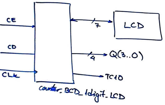 |
Fig 1. Symbol of the device to be designed. |
| Specifications | 2. Planning | Dev. & test | Prototype | report |
All planning is inherited from design phase #1 and no need to report it again. Let us focus simply on what changes and adaptation will imply interfacing the LCD.
A) Planning hardware
If we consider the CSD_PICstick board wiring, the simplest way to interface an LCD is to use PORTD, as represented in Fig. 1. The interface will be managed by high-level library functions. We will only write to the LCD, connecting RW = '0'. In this simple parallel interface we use six port D pins RD(5..0). A 10 kΩ potentiometer will adjust the LCD contrast to make the characters clear and visible.
  |
|
Fig. 2. Connecting 6 microcontroller port pins for the LCD interface. |
Optional, advanced, out of the CSD scope. Alternatively, to simplify the LCD hardware circuit interface, we can use the Inter-Integrated Circuit I2C serial communication bus to attach through a port expander the LCD as a client to the host mC. An example developed running the Microchip Code Configurator (MCC) Melody is presented in this DEE tutorial Counter_BCD_1digit_LCD.
B) Planning software
For this design step #1 where only static messages will be represented on the LCD screen, no new RAM variables are required.
 |
Fig. 3. Hardware-software diagram highlighting small modifications for connecting the LCD. Basically, the var_LCD_flag to be set only when new information is printed. The LCD is handled by specific functions from the LCD library. |
The state diagram is the same as it was in design phase #1 adding LCD instructions to print messages.
 |
Fig. 4. State diagram indicating the ASCII messages in each state. |
output_logic() generates an static ASCII message in each state.
state_logic() is the same, only clearing the LCD flag once used.
init_system() includes LCD initialisation.
read_inputs() to capture CE signal the same.
write_outputs() is the same because writing to the LCD is carried out by the LCD library routines.
ISR() to handle CLK edge detections is the same.
Organise a MPLABX - XC8 IDE project targeting a PIC18F46K22 at location:
C:\CSD\P11\counter_BCD_1digit_LCD\(files)
| Specifications | Planning | 3. Dev. & 4. test | Prototype | report |
A) Developing hardware
Parallel 6-wire interface. We will use the RD(5..0) through the expansion connector to interface the LCD. We need to find C libraries as it was proposed in P11. The reference and LCD libraries for this design are found here.
This is the "Counter_BCD_1digit_LCD.pdsprj" hardware circuit.
 |
| Fig. 8. Proteus schematic. |
B) Developing software
The XC8 compiler version is v3.0 or newer, C standard is C99. And these LCD library files "lcd.c", "lcd.h" has to be included in the project. The file "config.h" contains all the microcontroller configuration bits.
This "Counter_BCD_1digit_LCD.c " the software C source program.
 |
| Fig. 9. Library files and compiler options. To disable some warnings you can add these additional XC8 Compiler options: -Xparser -Wno-implicit-int-conversion -Wno-implicit-int-float-conversion. MPLAB XC8 C Compiler Use's Guide for PIC MCU. |
C) Step-by-step testing
 |
| Fig. 10. Proteus schematic running and watching RAM variables. |
| Specifications | Planning | Dev. & Test | 5. Prototype | Report |
| Specifications | Planning | Dev. & Test | Prototype | 6. Report |
Follow this rubric for writing reports.
| Home Term 26/27-Q1 Contact Products Electronic devices and companies Software Books Magazines Instruments DEE Library EETAC DEEL |

|
|
| Web activa des de 09/2001, @ F. J. Robert, Web editat amb Microsoft Expression Web 4. El contingut és un complement als materials d'estudi del curs Circuits i Sistemes Digitals disponibles al campus digital Atenea. Llicència:Reconeixement 4.0 Internacional de Creative Commons |