|
|
Bachelor's Degree in Telecommunications Systems and in Network Engineering |
|
|
|
|||||
Chapter 3 problems |
- D3.7 - |
Dumbwaiter or simple lift (μC - C) |
|||
|
|
|||||
1. Specifications
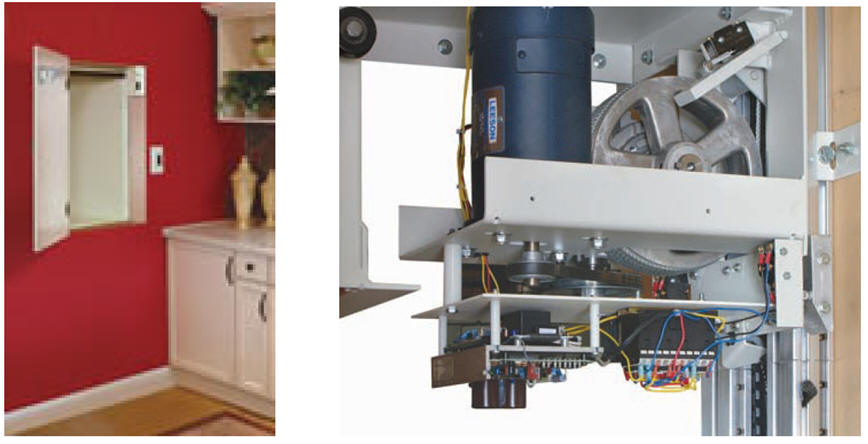
Our company has to design the control system for a simple dumbwaiter (a small freight elevator used to transport food, wine, and other items between storeys of a residential building) ordered by our client. It will transport loads between a 2-storeys kitchen. Fig. 1 shows a photograph of an installed commercial dumbwaiter and a detail of the motor and the control system installed under the car.
The same project designed using hardware is stated in D2.7.
 |
|
Fig. 1. Photograph of a commercial dumbwaiter. |
Some ideas to kick off the project and organise it.
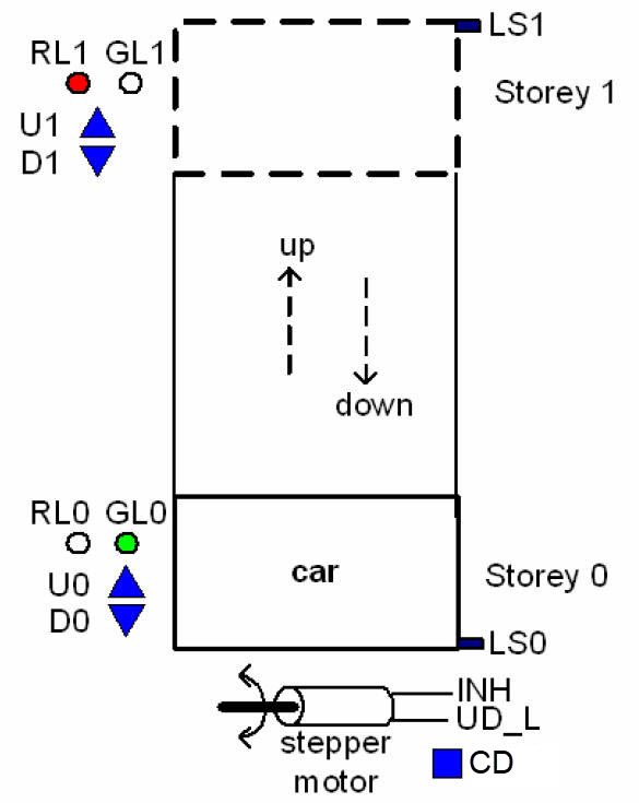
Produce a sketch of the dumbwaiter system that includes up and down buttons for both levels, location of the floor sensors, green and red LED's, and outputs for driving the stepper motor. See Fig. 2.
Sensors and buttons:
- U1, D1, U0, D0: buttons for calling the car.
- LS1, LS0: limit pushbuttons to detect the presence/absence of the car stopped at each storey. Interrupts.
Special signals:
- CD: if pressed or after power on, this special signal takes the car to the initial state stopping the car at storey 0.
- CLK: For polling buttons anc controlling the FSM. fCLK = 25 Hz.
Outputs for controlling the car motor:
- INH: when high this signal inhibits the motor movement.
- UD_L: when INH is not asserted, this signal generates up movement when high and down movement when low.
Additional visual outputs:
- GL1, RL1, GL0, RL0: LEDs for indicating operation: green LED is ON when the car is stopped in the corresponding storey, red LED is ON when the car is moving between storeys.
 |
|
Fig. 2. Sketch of the 2 storeys dumbwaiter indicating sensors, pushbuttons and output functions to drive the stepper motor and the LED. |
Draw the symbol of the entity to be designed.
Sketch a timing diagram showing the main operations.
Project location:
C:\CSD\P10\dumbwaiter\(files)
A) Planning hardware
Copy and adapt a circuit from a convenient tutorial project and name it dumbwaiter.pdsprj. Assign pins to inputs and outputs accordingly to one of the following options (your instructior will tell you which):
Pin assignment option #1:
LS0 --> RB2; LS1 --> RB1; CLK --> RB0;
U1 --> RC7; D1 --> RC6; U0 --> RB4; D0 --> RB3;
INH --> RA1; UD_L --> RA2
RL1 --> RC1; GL1 --> RC5; RL0 --> RA0; GL0 --> RB5;
Pin assignment option #2:
LS0 --> RB0; LS1 --> RB1; CLK --> RB2;
U1 --> RC6; D1 --> RC5; U0 --> RB7; D0 --> RB6;
INH --> RA2; UD_L --> RA0
RL1 --> RC7; GL1 --> RC4; RL0 --> RA3; GL0 --> RB5;
Pin assignment option #3:
LS0 --> RB1; LS1 --> RB0; CLK --> RB2;
U1 --> RC5; D1 --> RC4; U0 --> RB6; D0 --> RB3;
INH --> RA3; UD_L --> RA1
RL1 --> RC7; GL1 --> RC6; RL0 --> RB4; GL0 --> RC1;
Draw the hardware schematic. Buttons and switches, resistors, inputs, outputs, reset circuit MCLR_L and quartz crystal oscillator of 8 MHz. Explain how to configure inputs and outputs in init_system().
B) Planning software
Draw the flowchart of the general program organisation.
Draw and explain the hardware-software diagram. Explain the difference between variables and flag variables.
Infer the state diagram governing the machine.
Explain how to poll (read) the storey buttons in read_inputs() using bitwise operations. Explain how to measure how many times per second these switches are read.
Explain how to drive output pins in write_outputs().
Explain the external interrupt mechanism for connecting the limit sensor buttons. Explain how the ISR() is used.
Draw the state_logic() truth table and its equivalent flowchart ready for translation to C language.
Draw the output_logic() truth table and its equivalent flowchart ready for translation to C language.
Developing & testing (debugging)
Develop and test (debugging) the project capturing the hardware circuit in Proteus and writting the C source code.
| Note: Step-by-step tactical approach for developing and testing the project: Read one input at a time and run to check that the voltage value is correctly captured as a valid digital value in RAM memory. Write one output at a time and run to check that your code is correct to light the LED connected at the output pin. |
Design phase #2: an LCD will indicate ASCII messages and numbers. In this application, we should install an LCD screen at each storey. However let's imagine only one at storey 0.
Explain how to connect and program the LCD display to show ASCII messages such: "Car stopped at storey 0", "moving UP", "Close door when ready", etc. on the screen such: "PLAY", "STOP", etc.
While the car is moving up or down, display as a number the downcount of the seconds left before stopping in the storey.
Design phase #3: using internal peripheral TMR2
Configure and program TMR2 to replace the external CLK oscillator. Explain whether new states are required.
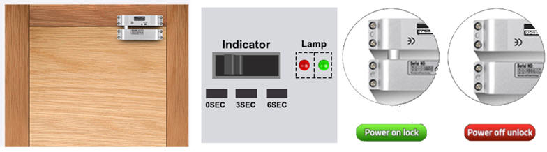
Optional: A security enhancement for preventing user accidents can be added in a new design phase #2. Install sensors switches (DS1, DS0) and electric drop bolt locks (DL1, DL0) in the storey doors, so that the car does not move unless doors are closed, and they do not open while the car is in transit or is not yet stopped in the corrresponding storey.
 |
|
Fig. 5. Example of an storey door secured with an electric drop bolt lock (ref.). The idea is to keep the storey doors closed while the car is in transit |
| Home Term 24/25-Q1 Contact Products Electronic devices and companies Software Books Magazines Instruments DEE Library EETAC DEEL |

|
|
| Web activa des de 09/2001, @ F. J. Robert, J. Jordana. Web editat amb Microsoft Expression Web 4. El contingut és un complement als materials d'estudi del curs Circuits i Sistemes Digitals disponibles al campus digital Atenea. Llicència:Reconeixement 4.0 Internacional de Creative Commons |