|
|
Bachelor's Degree in Telecommunications Systems and in Network Engineering |
|
|
|
|||||
Chapter 2 problems |
- D2.13 - |
Programmable timer (FPGA-VHDL) |
|||
|
|
|||||
1. Specifications
The user enter a three digit number from a numerical keypad. Then clicks start (ST) to down counting from the number entered. While downcounting a LED is blinking with 0.6 s period.
In a design phase #2 this feature can be considered: when zero is reached, a 1.2 kHz sound wave drives a buzzer for 5 s.
The same project designed programming a μC is in D3.13.
Some ideas to kick off the project:
Indeed, this application is a timer device based on a 3-digit BCD down-counter, and its structure and components will be similar to P8 highlighter project. We can imagine that this instrument, in its first design phase is counting in seconds, thus the maximum number is 999 s.
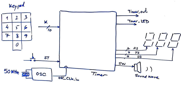 |
| Fig. 1. Initial sketch representing the symbols and the main signals. |
An idea of the waveforms from the circuit is represented in Fig. 2. We can imagine that in an initial state the machine is sampling the keypad: the digits are shifted from units to hundreds and last three captured digits represent the timing period in seconds.
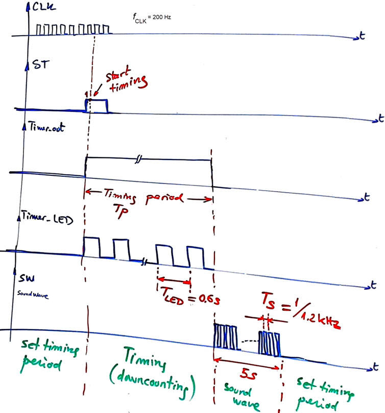 |
| Fig. 2. Example of initial timing diagram. The 1.2 kHz SW signal can be generated in a design phase #2. |
A way to start capturing digits is considering the hardware in Fig. 3. We have an Enc_10_4 whatever combinational (DT2.5, L2.3) or matrix (P6). When the user is clicking a key, GS = '1'. We can use this signal to control the sequence of states and be able to save in Data_Reg_4bit and shift left the digits inputted. We also may consider that at any time the user can click the start button ST to generate the timing period TP at Timer_out, the LED intermitency at Timer_LED and the sound waveform at SW.
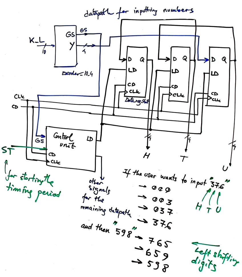 |
| Fig. 3. Example of datapath hardware sketch for saving and shifting left digits. In this case for capturing input information, the seconds count to time. The key concept is that LD = '1' only for one CLK period when the user is clicking. The digit chain can be expanded to the desired number of digits. |
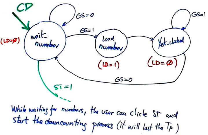 |
| Fig. 4. Convenient initial state diagram to capture digits when the key is clicked. It works a loop capturing and shifting left digits. It has to be continued to control the remaining circuits of the datapath when the user presses ST = '1'. |
Naturally, the complete datapath circuit will also include the Counter_BCD_3digit with parallel load (LD) and Din. It is sketched in Fig. 5. In this project, this Chip5 is the main component. Thus it is a good idea to design and test it as an individual project in an initial design step. We can invent it only for down-counting operations (no need of UD_L control signal).
- How to design the Counter_BCD_3digit chaining/expanding 1-digit BCD counters from this Counter_BCD_1digit plan Y tutorial adding the parallel load LD?
- Or, how to design it studying and adapting the Hour_counter P7 highlighted project based on Counter_mod16?
Only when Chip5 is fuly tested and working correctly we can use it in this application.
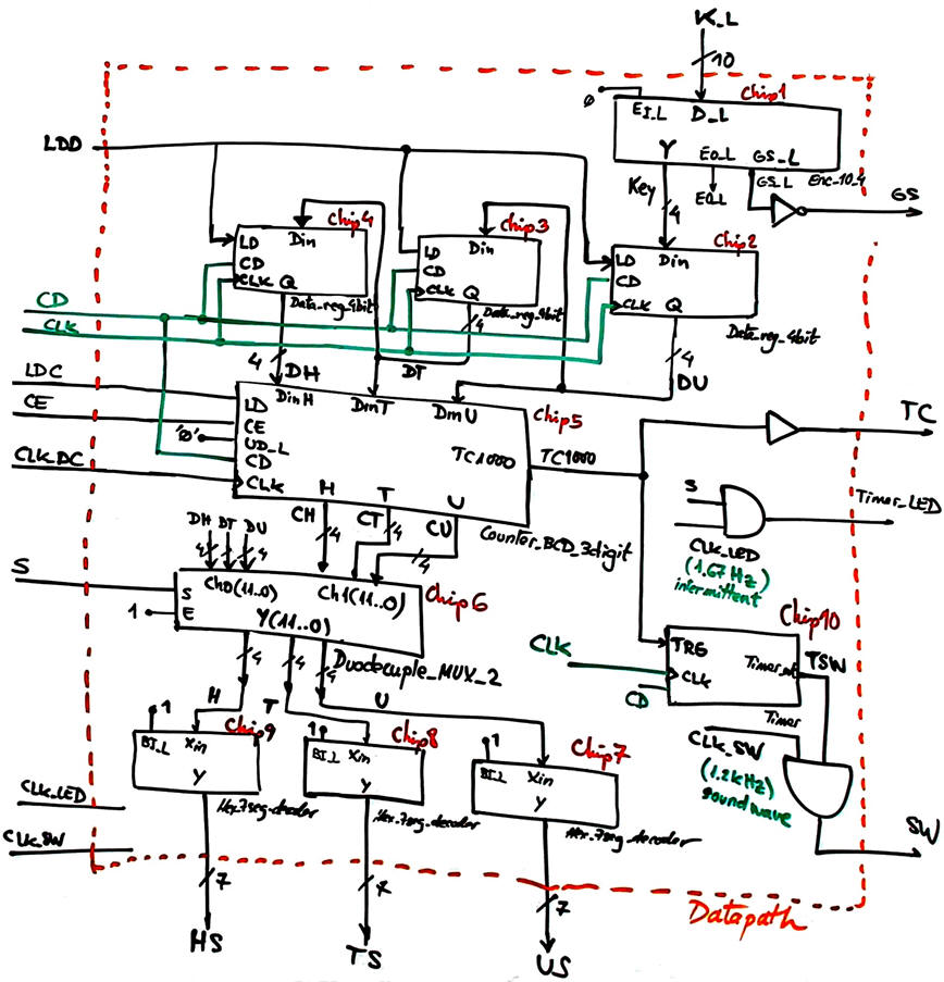 |
| Fig. 5. Example of internal design of the Datapath circuit, an operational unit that encodes, decodes, count, select and register the data from the keypad. The control unit (FSM) will order and organise the sequence of operations. The 5 s timer for controlling the soundwave can be included in a design phase #2. |
In this way, we can deduce and draw as shown in Fig. 6 a possible dedicated processor for solving the main tasks of this timer/down-counter.
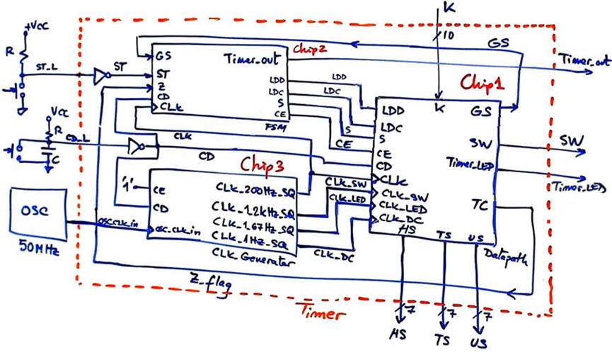 |
| Fig. 6. Example circuit for a dedicated processor. |
The control unit (FSM) can run an state diagram as shown in Fig. 7. The status signal Z_flag from the datapath indicates when the cdowncount has reached zero (terminal count) to stop timing and trigger on the falling edge the 5 s timer that will enable the sound wave (TSW).
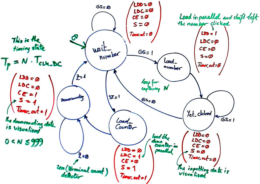 |
| Fig. 7. Only once the hardware is invented we can imagine the required states to control and run this application. |
In a first version of the CLK_Generator you can generate only one CLK signal, for example CLK_200Hz_SQ to run both the FSM and the datapath. In this way you can check whether the operations of reading and saving digits, loading the counter and downcounting work correctly.
Design phase #2: Include the 5 s timer that controls the sound waveform (SW) output.
Optional design phase #3: How to enhance the circuit to generate accurate pulses in nanoseconds (ns), microseconds (μs) and miliseconds (ms). The concepts of accuracy, precision, resolution and sensitivity in instrumentation.
| Home Term 24/25-Q1 Contact Products Electronic devices and companies Software Books Magazines Instruments DEE Library EETAC DEEL |

|
|
| Web activa des de 09/2001, @ F. J. Robert, J. Jordana. Web editat amb Microsoft Expression Web 4. El contingut és un complement als materials d'estudi del curs Circuits i Sistemes Digitals disponibles al campus digital Atenea. Llicència:Reconeixement 4.0 Internacional de Creative Commons |