|
|
Bachelor's Degree in Telecommunications Systems and in Network Engineering |
|
|
|
|||||
Chapter 3 problems |
- D3.2 - |
Stepper motor controller (μC - C) |
|||
|
|
|||||
1. Specifications
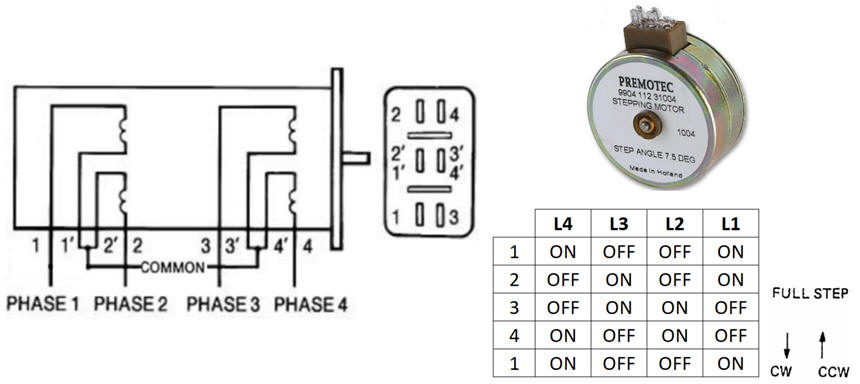
Our aim is to design the digital control unit (stepper_controller) for the "9904 112 31004" stepping motor from Premotec shown in Fig. 1 following our microcontroller-based strategy. Nowadays stepper motors can be found in computer peripherals, machine tools, medical equipment, automotive devices, or small business machines, to name a few applications.
The same project designed using hardware is stated in D2.2.
Clockwise (CW) and counter-clockwise (CCW) rotation can be achieved by reversing the step sequence. Inhibit (INH) is like a count disable, do not letting the motor rotate. Step or stride angle is 7.5 degree, thus 48 CLK periods are required for a full revolution. External CLK frequency is 96 Hz, and so when running it rotates at 2 revolutions per second.
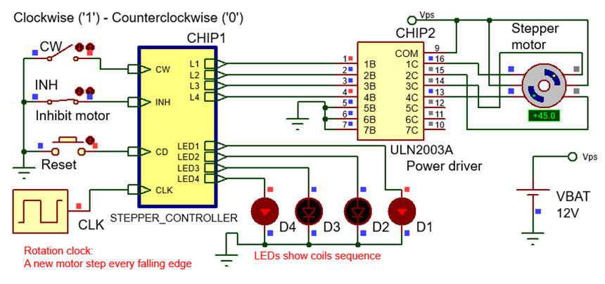
The idea is to connect four port pins to the motor coils and drive them with the right sequence so that the motor inhibits or rotates clockwise or counter-clockwise accordingly to the input signals INH and CW. Four additional pins are used connected to LED to visualise the coils binary sequence.
In an additional design phase, the external CLK oscillator will be replaced by the internal peripheral TMR0.
 |
|
Fig. 1. Example of two-phase stepper motor: characteristics, connections, full wave steeping sequence and unipolar winding circuit using a power driver to energise coils. |
Design phase #1: Some questions to kick off the project and organise it in four sections. You can conceive this project phase consisting of 2 design steps:
- step #1: continuous clockwise rotation with also switch INH and pushbutton or CLK
- step #2: Add switch CW to be able to run clockwise and counterclockwise.
a) Draw the schematic: input switches, outputs, reset (MCLR_L) and 4.8 MHz quartz crystal oscillator OSC.
 |
|
Fig. 2. Schematic including the power driver ULN2003A. |
b) Draw the hardware-software diagram. Why the rotation CLK block has to be connected to RB0/INT pin? What the interrupt service routine ISR() is used for?
c) Organise and name RAM variables for the project. Explain how to configure port pins and interrupts in init_system().
d) Explain how to poll the input values using bitwise operations in read_inputs().
e) Explain how to drive the eight outputs using bitwise operations in write_outputs().
f) Draw the truth table and flowchart for the output_logic().
 |
|
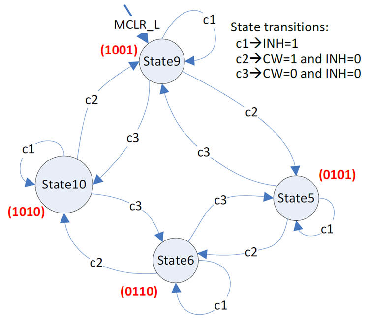
Fig. 3. Example of FSM state diagram. |
g) Draw the truth table and flowchart for the state_logic().
h) Develop and test (debugging) the project capturing the hardware circuit in Proteus and writting the C source code.
Design phase #2 an LCD will indicate ASCII and numerical messages about the motor operation.
i) Enhance the schematic from design phase #1 to include an LCD attached to port D as studied in tutorials.
j) Enhance the software and the source file to drive the LCD.
In this design phase also two design steps may be conceived, for instance:
- step #1: Print ASCII messages on the LCD.
- step #2: Print as well the rotation speed calculated from the CLK.
Design phase #3, the external CLK oscillator circuit will be replaced by internal peripherals TMR2. In this way, we will save power consumption, reduce board footprint, and also free an external INT for other future applications.
k) Replace the external CLK configuring TMR2 to obtain the same 96 Hz step frequency.
l) You can add other features, for instance, if the motor is INH for more than two minutes, a sound signal 2 kHz for a buzzer will be triggered.
| Home Term 24/25-Q1 Contact Products Electronic devices and companies Software Books Magazines Instruments DEE Library EETAC DEEL |

|
|
| Web activa des de 09/2001, @ F. J. Robert, J. Jordana. Web editat amb Microsoft Expression Web 4. El contingut és un complement als materials d'estudi del curs Circuits i Sistemes Digitals disponibles al campus digital Atenea. Llicència:Reconeixement 4.0 Internacional de Creative Commons |