|
|
Bachelor's Degree in Telecommunications Systems and in Network Engineering |
|
|
|
|||
|
|
P12: using peripheral timer TMR2 |
|
|
|
|
|||
4-bit serial transmitter with LCD and TMR2 (design phase #4)
1. Specifications
This is an example of design phase #4: replace TMR0 in s_trans_LCD_TMR0 proposed in design phase #3, by the internal timer peripheral TMR2.
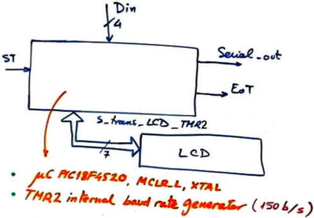 |
Fig. 1. Project s_trans_LCD_TMR2 symbol (entity name is shortened for not reaching Windows naming length limit). |
2. Planning
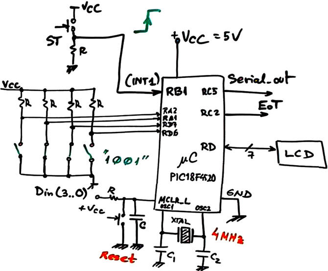
A) Planning hardware
The electronic schematic is the same as in design phase #3, we simply replace an internal peripheral by another, thus keeping the same hardware circuit.
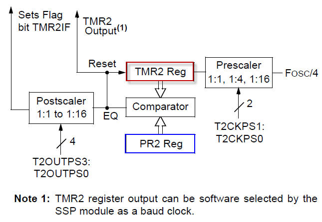
Study how the TMR2 works. It has an architecture that implements a hardwired paralle load (LD) signal or synchronous reset that makes it ideal for truncated counting using an additional 8-bit comparator. No software overhead is necessary in ISR() for reinitialing the up counter TMR2 when reaching the same value stored in PR2 register.
|
|
|
Fig 2. Hardware components (a kind of RTL view) of the TMR2 of the Microchip PIC18F4520. |
The key idea for our application is to geneate the same var_CLK_flag from TMR2 interrupts.
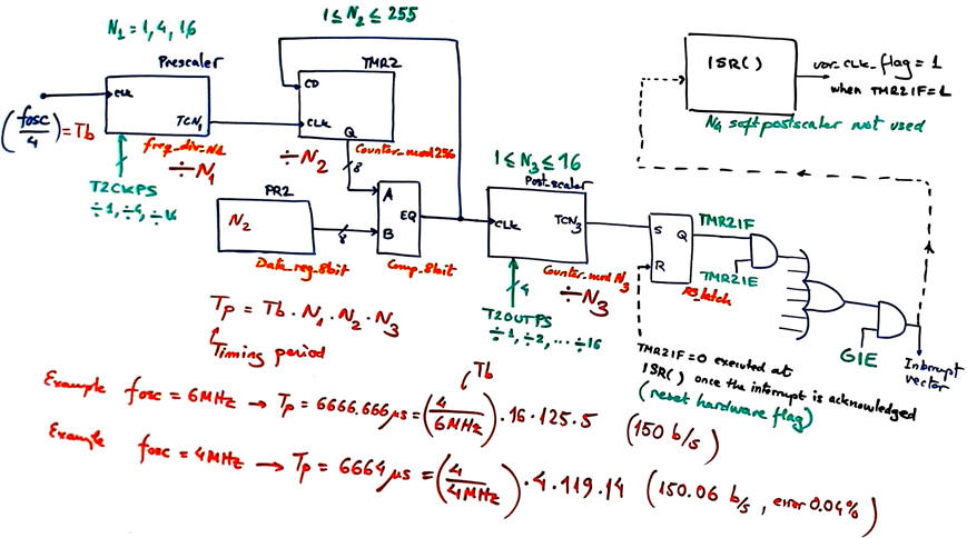 |
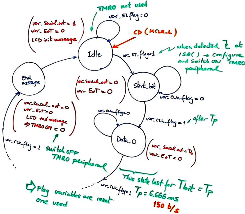
Fig. 2. TMR2 configuration for generating a timing period TP = 6.666 ms. In this application, no extra software post-scaler variable N4 is required. |
B) Planning software
No changes in the state diagram from design phase #3. We simply have to configure and use TMR2 at the same states where we did it for TMR0.
Project location:
C:\CSD\P12\s_trans_LCD_TMR2\(files)
3. Developing and 4. Testing the design using EDA tools
A) Developing hardware
Our electronic circuit s_trans_LCD_TMR2.pdsprj is the same that we developed in design phase #3 becasue we simple replace internal peripheral TMR0 by TMR2.
B) Developing software
This is an example of project source code s_trans_LCD_TMR2.c where we have simply enabled, configured and used TMR2 where previously had TMR0. This project must include LCD libraries as well.
C) Step-by-step testing
We can run and debug the application using our usual resources and tools: breakpoints, step-mode, watching variables of interest, etc. For instance, Fig. 3 shows how to measure timing periods generated between TMR2 interrupts.
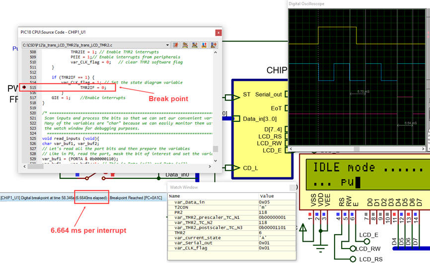 |
Fig. 3. Measuring timing periods generated by TMR2 interrupts using breakpoints. There is an interrupt event every TP = 1μs · 4 · 119 · 14 = 6664 μs as expected. |
5. Report
6. Prototyping
| Home Term 25/26-Q1 Contact Products Electronic devices and companies Software Books Magazines Instruments DEE Library EETAC DEEL |

|
|
| Web activa des de 09/2001, @ F. J. Robert, Web editat amb Microsoft Expression Web 4. El contingut és un complement als materials d'estudi del curs Circuits i Sistemes Digitals disponibles al campus digital Atenea. Llicència:Reconeixement 4.0 Internacional de Creative Commons |