|
|
Bachelor's Degree in Telecommunications Systems and in Network Engineering |
|
|
|
|||||
Chapter 2 problems |
- D2.2 - |
-- Stepper motor controller (FPGA -VHDL version) |
|||
|
|
|||||
1. Specifications
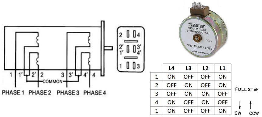
Our aim is to design the digital control unit (stepper_controller) for the "9904 112 31004" stepping motor from Premotec shown in Fig. 1 following our FSM strategies. Nowadays stepper motors can be found in computer peripherals, machine tools, medical equipment, automotive devices, or small business machines, to name a few applications. Clockwise (CW) and counter-clockwise (CCW) rotation can be achieved by reversing the step sequence. Inhibit (INH) is like a count disable, do not letting the motor rotate. Step or stride angle is 7.5 degree, thus 48 CLK periods are required for a full revolution. External CLK frequency is 96 Hz, and so when running it rotates at 2 revolutions per second.
The idea is to connect four outputs to the motor coils and drive them with the right sequence so that the motor inhibits or rotates clockwise or counter-clockwise accordingly to the input signals INH and CW. Four additional outputs are used connected to LED to visualise the coils binary sequence.
 |
|
Fig. 1. Example of two-phase stepper motor: characteristics, connections, full wave steeping sequence and unipolar winding circuit using a power driver to energise coils. |
Some questions to kick off the project and organise it in four phases:
1. Draw the circuit symbol and an example of timing diagram.
 |
|
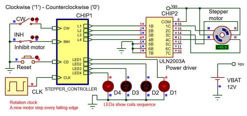
Fig. 2. Schematic including the power driver ULN2003A. |
2. Draw an example state diagram for this appliction.
 |
|
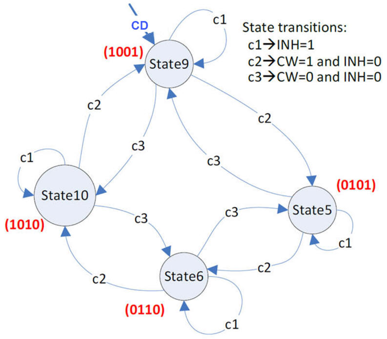
Fig. 3. Example of FSM state diagram. |
3. Apply the FSM architecture to this problem and draw the state register based on D_FF. Deduce how many D_FF are required if coding states in one-hot.
4. Write the truth table of CC1 and CC2 and their equivalent behavioural interpretations using flowcharts.
5. Write the FSM VHDL file and develop the circuit for a Cyclone IV target chip using EDA tools. Inspect the RTL and technology views. How many D_FF registers are used in this application?
6 Generate a VHDL testbench fixture to demonstrate that the circuit operates correctly.
7. In an additional phase, design the CLK generator circuit from a 50 MHz quartz crystal oscillator to obtain the 96 Hz CLK signal. Deduce the number of D_FF that it will contain.
HINT: Firstly you can organise this project as "design phase #1" (without CW switch), where there is only clockwise rotation. And only when this phase #1 works correctly and you have completed sections 1-2-3-4-5-6, you can infer what is necessary to add and modify to connect another switch CW for selecting the rotation direction. This is again the idea of going step-by-step.
8. In an additional design phase, the stepper_controller rotating speed may be programmable using an 8-bit data input S(7..0). Discuss how to implement such enhancement: a programmable speed generator. What may be the maximum speed of rotation for a given commercial stepper motor?
| Home Term 23/24-Q2 Contact Products Electronic devices and companies Software Books Magazines Instruments DEE Library EETAC DEEL |

|
|
| Web activa des de 09/2001, @ F. J. Robert, J. Jordana. Web editat amb Microsoft Expression Web 4. El contingut és un complement als materials d'estudi del curs Circuits i Sistemes Digitals disponibles al campus digital Atenea. Llicència:Reconeixement 4.0 Internacional de Creative Commons |