|
|
Bachelor's Degree in Telecommunications Systems and in Network Engineering |
|
|
|
|||||
Chapter 1 problems |
- D1.11 - |
10-bit arithmetic circuit for radix-2 and integer numbers |
|||
|
|
|||||
1. Specifications
Design using plan C2 the 10-bit selectable adder subtractor comparator named Sel _add_subt_comp_10bit represented in Fig. 1a, a simplified arithmetic unit, targeting the given FPGA chip.
The same project B3.11 is proposed in Chapter 3 for learning the basics of μC software organisation and basic digital I/O.
 |
|
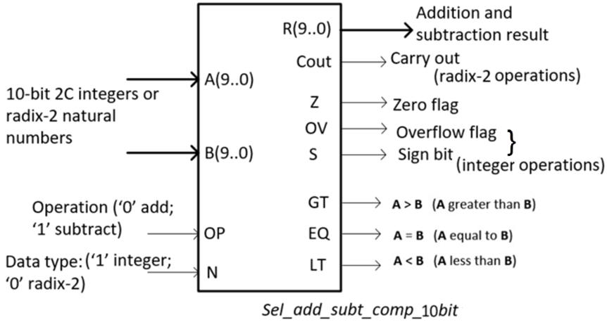
Fig. 1a. Arithmetic circuit for 10-bit radix-2 and integer numbers. |
The circuit truth table signals are ordered as shown in Fig. 1b. Generate half of the table for N = '0' (data type radix-2) and the other half with N = '1' (data type integers). An example of table representation is in the highlighted P4.
|
Fig. 1b. Input and output order in the truth table. |
What is the range of operands and results?
You can consider several options for the test vectors, such:
option #1: Radix-2 numbers for N = '0': 987, 345, 23, 1, 0, 14, 1023. Integer numbers for N = '1': (+33), (-33), (+510), (-510), (+92), (-39), 0
option #2: Radix-2 numbers for N = '0': 333, 999, 45, 6, 0, 414, 1023. Integer numbers for N = '1': (+111), (-222), (+333), (-512), (+511),( -39), 0
option #3: Radix-2 numbers for N = '0': 88, 777, 556, 12, 0, 433, 1023. Integer numbers for N = '1': (+99), (-99), (+444), (-444), (-511), (-18), 0
Draw the truth table. How long is it?
Draw an example of timing diagram to be used later as stimulus in the VHDL testbench when verifying the synthesised circuit. Suppose that Min_Pulse = 2.21 μs. How long does it take to simultate all the table combinations?
CPLD or FPGA target chip options:
option #1: MAX II
option #2: Cyclone IV
option #3: MAX 10
2. Planning
Many arithmetic components are available in P4 and P3. And so, the idea is to apply our Plan C2 to draw a hierarchical top schematic based on components and signals.
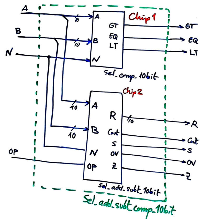
The top entity may be conceived separating comparisons and additions/subtractions as shown in Fig. 2.
 |
|
Fig. 2. Project top entity architecture. |
In this way, we can tackle the project divided in two main components. The idea of coparing natural numbers and integers in the same block, can be layed out in Fig. 3.
 |
|
Fig. 3. The idea of data type selection for comparison operations. |
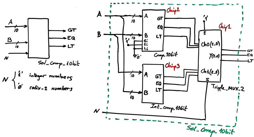
The conceptual idea in Fig. 3 can be optimised because comparing integer numbers using a radix-2 comparators is not that difficult: see the algorith in this example Int_comp_8bit.
 |
|
Fig. 4. Optimised circuit for comparing integer and natural numbers. |
The idea on how to implement an adder/subtractor for integer numbers is explained in this highlighted project: Int_add_subt_8bit. Only expanding the circuit size to 10-bit is required.
And thus, we can infer how to organise a module valid for both data types in Fig. 5.
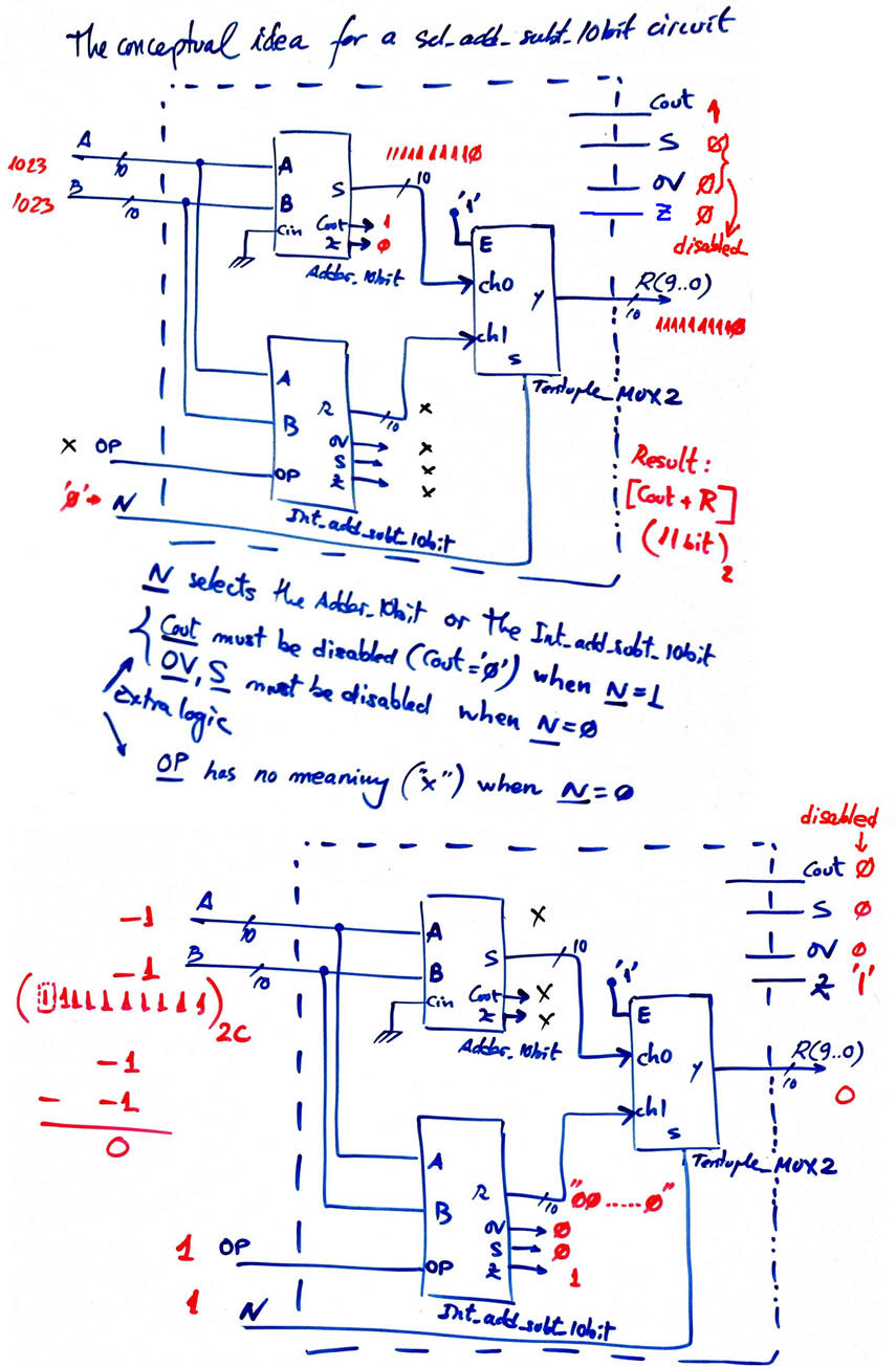 |
|
Fig. 5. The conceptual idea of designing a circuit valid for two data types. |
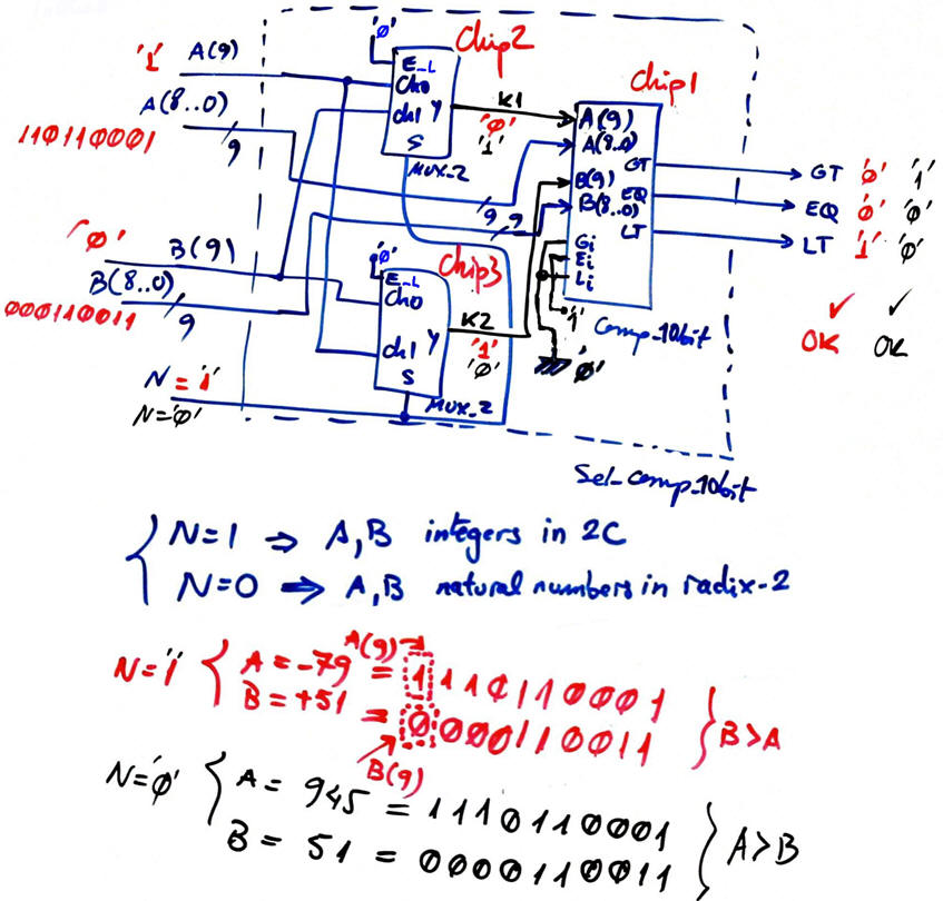
And, in the same way we did for the comparator, we can optimise the architecture of the sel_add_subt_10bit as represented in Fig. 6. Some control gates allow disabling the flag signals of no interest.
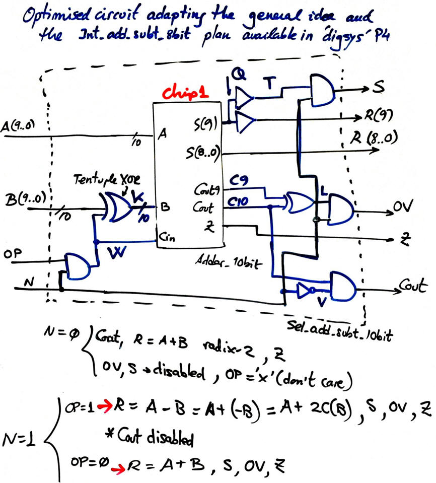 |
|
Fig. 6. Optimised adder-subtractor to reduce the component count. |
Combining Fig. 6 as Chip2 and Fig. 4 as Chip1 we complete the top entity for this project in Fig. 2.
Let us consider these options:
option #1: Comp_4bit ---> plan A equations architecture; Comp_10bit ---> plan C2 reducing the 24-bit tree architecture shown in 74F85 datasheet to only 10-bit; Adder_4bit ---> plan C2 carry lookahead (CLA)
Project location:
C:\CSD\P3\Sel_Add_Subt_Comp_10bit\Opt1\(files)
option #2: Comp_10bit ---> plan C2 ripple architecture using Comp_1bit based on the MoM; Adder_10bit ---> plan C2 ripple carry (RC) using Adder_1bit.
Project location:
C:\CSD\P3\Sel_Add_Subt_Comp_10bit\Opt2\(files)
3. Development
Circuit synthesis
4. Test (functional)
Functional simulation
After having studied P4 lectures and LAB4 tutorials, the project can continue adding the fifth section on time measurements.
5. Test (gate-level)
Additional questions can be added to our report. For instance:
-
Perform a gate-level simulation to measure propagation delays in a given signal transition.
-
Deduce the worst-case propagation delay running the timing analiser tool and calculate the circuit's maximum frequency of operation for the target chip used in the design.
-
In the end, because two alternative internal circuit architectures are proposed (option #1:CLA, option #2: RC, we can compare which one is faster and which one uses less resources (logic elements).
-
And also, for each circuit architecture, because we are proposing several target chips (option #1: MAX II, option #2: Cyclone IV) you can measure which technology is faster. Unfortunately, the family MAX10 does not generate the required standard delay files (-sdo) for running gate-level simulations.
| Home Term 24/25-Q1 Contact Products Electronic devices and companies Software Books Magazines Instruments DEE Library EETAC DEEL |

|
|
| Web activa des de 09/2001, @ F. J. Robert, J. Jordana. Web editat amb Microsoft Expression Web 4. El contingut és un complement als materials d'estudi del curs Circuits i Sistemes Digitals disponibles al campus digital Atenea. Llicència:Reconeixement 4.0 Internacional de Creative Commons |