|
|
Bachelor's Degree in Telecommunications Systems and in Network Engineering |
|
P11: peripheral LCD and C libraries for specialised functions. |
| Resources in lectures and labs: | L11, Lab11 | Project | objectives |
Highlighted project: 4-bit serial transmitter with LCD display
Design phases ==> #1: Serial_TX ==> #2: Serial_TX_LCD ==> #3: Serial_TX_LCD_TMR0 ==> #4: Serial_TX_LCD_TMR2
| 1. Specifications | Planning | Dev. & test | Prototype | Report |
Design phase #2: Serial_TX_LCD
-
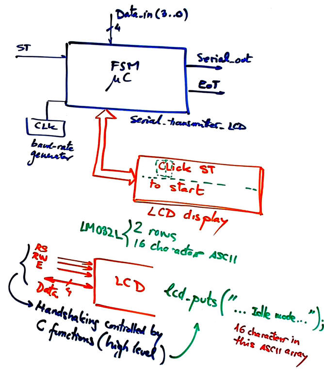
Enhance the Serial_TX from design phase #1 adding a standard LCD display to represent ASCII messages on the two-line 16-character screen. Information can be about the internal state, for example: "Click ST button to start", "Current state: Idle", "End transmission", etc. Full tutorial recording rec.
-
Modify the hardware to connect the signals to drive the LCD display. Let us use the CSD_PICstick for prototyping.
-
Program the application using the LCD library of the C compiler (for instance the XC8 Compiler for the PIC18F46K22).
-
Use a var_LCD_flag signal to write the LCD only when there is new information to be printed; communicating with the LCD is a slow operation that cannot block the FSM main loop.
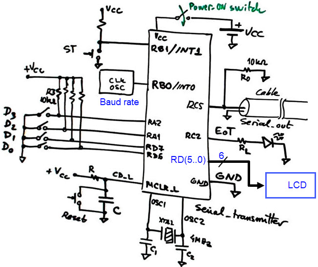
The new symbol Serial_TX_LCD is represented in Fig. 1.
|
|
|
Fig 1. Adding an external LCD peripheral to the basic 4-bit serial transmitter from P10. It implies adding new connections to the chip, for instance PORTD pins, and new functions in the source file from an external library, therefore, compiling a hierarchical multiple-file project (equivalent to our plan C2 in previous hardware projects). |
The common display kit LM1602L is presented in Fig. 2.
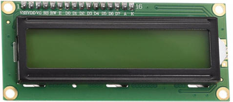 |
Fig. 2. The LCD controller chip is the standard Hitachi HD44780 (Dot Matrix Liquid Crystal Display Controller/Driver) or equivalent like the HD44100. Some displays include LED background illumination (pin 15, A; pin 16, K). V0 is used to adjust the display contrast by means of a potentiometer. |
 |
|
We can use only a 4-bit bus to send commands or data to the LCD. The low-level communication protocol will be solved using a C language library of functions. It requires up to seven pins for handshaking and data. Optionally, the microcontroller can use another output port pin to switch on and off the LCD power supply to save energy if required.
|
|
|
Fig 3. LCD parallel interface. Note: if only writing to the device is required, the control signal R/W (RW_L) can be connected permanently low (RW_L = '0'), thus six port pins are necessary for this parallel interface. Datasheet: (1). |
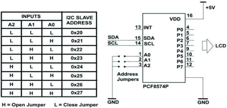
Optional, advanced, out of the CSD scope. Alternatively, to simplify even further the LCD hardware circuit interface, we can use the Inter-Integrated Circuit I2C serial communication bus to attach through a port expander the LCD as a client to the host mC. An example developed running the Microchip Code Configurator (MCC) Melody is presented in this DEE tutorial Counter_BCD_1digit_LCD. Other examples of this kind are solved for the Arduino platform.
|
|
|
Fig 4. Serial I2C adapter based on the PCF8574 port expander chip. |
Other design tutorials and assignments.
| Specifications | 2. Planning | Dev. & test | Prototype | report |
A) Planning hardware
As in previous projects, draw your circuit in a sheet of paper and discuss where to connect: reset (CD_L or MCLR_L), OSC oscillator, digital I/O and push-buttons. We can use free pins from the CSD_PICstick board and reserve some PORTD pins to connect the LCD.
  |
|
Fig. 5. Connecting RD(5..0) pins to interface the LCD. |
B) Planning software
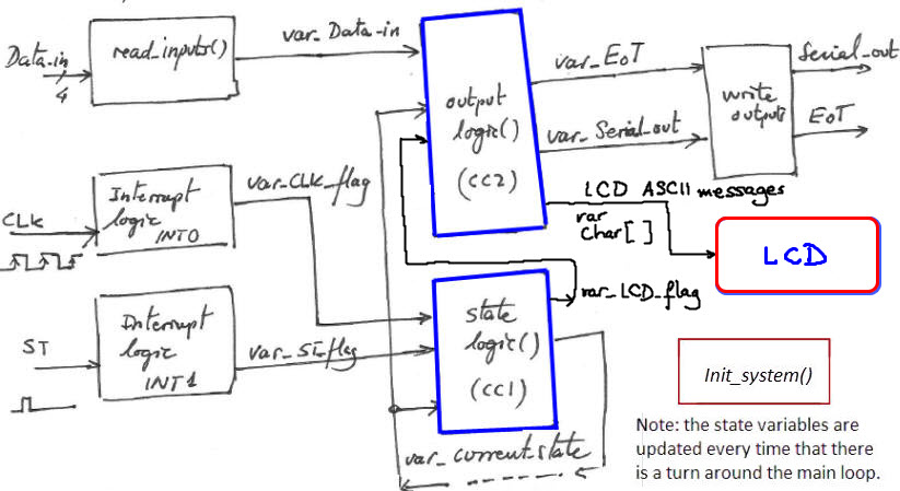
Determine the functions in the main program that have to be modified in order to control the LCD display. Define RAM internal variables to facilitate LCD communication. Use a convenient indicator like var_LCD_flag to prevent writing continuously to the display; this flag is set only when new information has to be shown. For example Fig. 5 shows the hardware-software diagram. Output_logic() generates the variables to interface with LCD high-level functions.
 |
|
Fig. 5. Hardware-software diagram. |
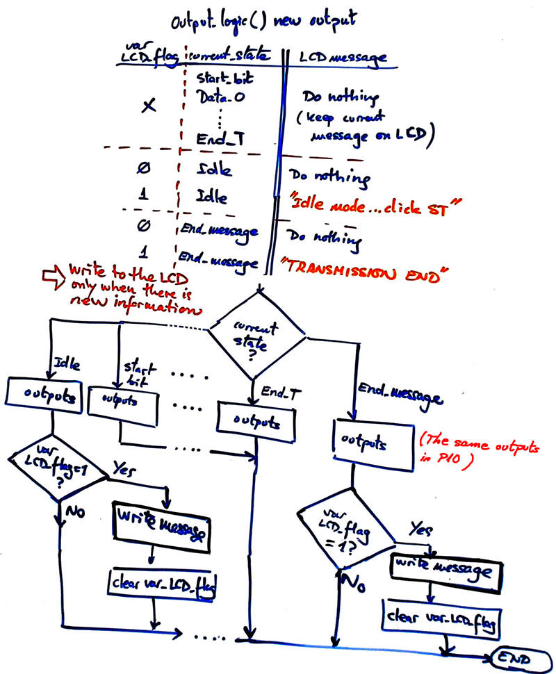
And Fig.6 represents the truth table and its flowchart.
|
|
|
Fig 6. Output_logic() function. The new variable var_LCD_flag is required to write the LCD only when new information is available. The flowchart must solve the idea. |
Plan a sequence for building and debugging the application: the idea is "plan & develop & test" step by step enhancing the initial state diagram with a new feature at a time. For instance:
Step #1 to check that your MPLABX IDE and Proteus environments work correctly. Start running the copy of the phase #1 project in the new location updating project and file names; try to print only the typical ASCII message "Hello World" on the LCD. How long does it take to write a message at the LCD? How can you measure such execution time? Why a var_LCD_flag is required?
Step #2 Add now the messages you like in FSM states or add new states when necessary.
Step #3 Add numerical information on the display, mixing text and dynamic data, for instance in this example a count of the messages transmitted.
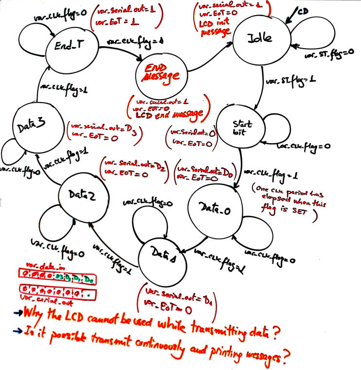
Fig. 7 below is a possible state diagram modified from P10 to allow printing ASCII messages beginning and ending transmissions.
|
|
|
Fig. 7. State diagram to print ASCII messages on the LCD. |
Organise an MPLABX - XC8 IDE project targeting a PIC18F46K22 at the new location (remember to start copying both hardware and software files from the previous design phase; then, update project names and files).
C:\CSD\P11\Serial_TX_LCD\(files)
| Specifications | Planning | 3. Dev. & 4. test | Prototype | Report |
A) Developing hardware
Draw the schematic of the application in Proteus copying the P10 and modifying it accordingly to your new sketch in paper that includes the LCD connections. so that the LCD is made visible on the top schematic. Fig. 8 shows an example circuit "Serial_TX_LCD.pdsprj".
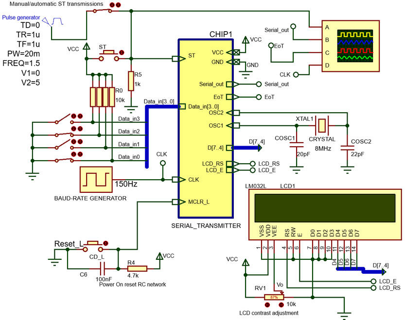 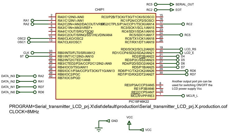 |
Fig. 8. Captured circuit in Proteus. Here we have two options for triggering transmissions: a manual ST button or an periodic train of pulses. |
B) Developing software
Translate to C language your new flowcharts. Run the microcontroller's IDE MPLABX to develop and compile the C code copying and adapting the previous P10 code. Do it section by section according to your plan, testing whether it works before adding new code. The entity Serial_TX becomes now in this new design phase Serial_TX_LCD.
|
|
|
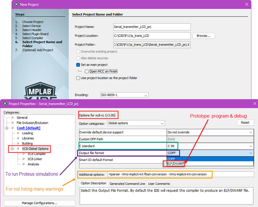
Fig 9. XC8 project options to generate the COF file to run Proteus simulations. |
In Fig. 10 is an example list of source files when using the libraries to interface this specific LCD hardware.
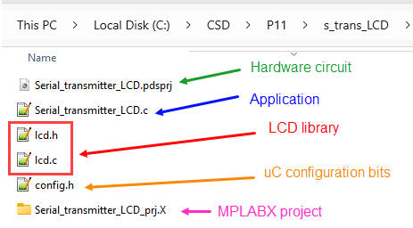 |
Fig. 10. Example of a typical project that includes LCD libraries to drive specific and advanced hardware subsystems (peripherals), thus, becoming a multiple-file project, as a kind of software plan C2 with several components (functions) under the top schematic. |
The current XC8 compiler version is v3.1, C standard is C99. And these LCD library files "lcd.c", "lcd.h" have to be included in the project. The file "config.h" contains all the microcontroller configuration bits.
This "Serial_TX_LCD.c" is an example C code translating the planned FSM.
|
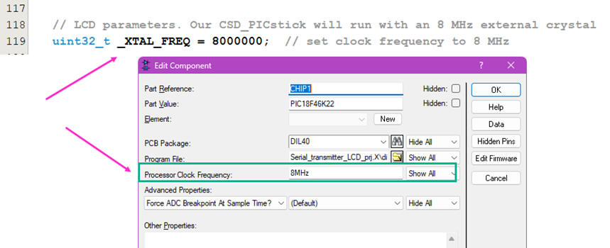
|
Fig 11. Edit the variable _XTAL_FREQ to be of the same value set in the hardware circuit (PIC18F46K22 parameter Processor Clock Frequency). |
This "Serial_TX_LCD.zip" is the full zipped project.
C) Step-by-step testing
Run the Proteus simulator. Do it in step by step mode while watching variables and placing break points, specially to follow the interrupt flags.
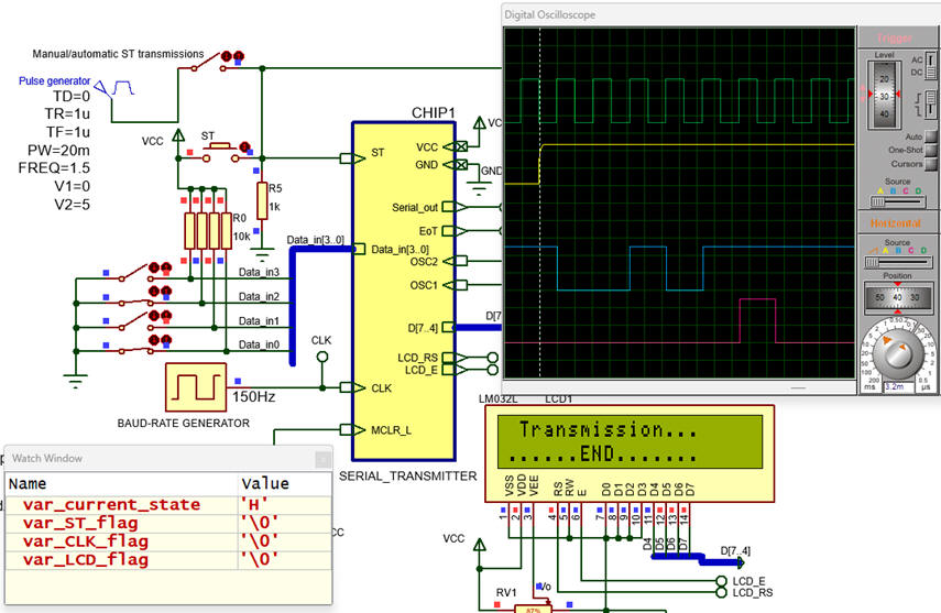 |
|
Fig. 12. Circuit running and showing ASCII messages in the LCD display. |
Learn how to use the One-shot (single) trigger operation mode of the oscilloscope and how the frame of bit is transmitted once the ST button is detected. Can you add a pulse generator to automate ST pulses (20 ms duration, 1.5 Hz) ?
Measure how long does it take to write one row of 16 ASCII characters to the LCD screen.
| Specifications | Planning | Dev. & Test | 5. Prototype | Report |
Example 1: Board CSD_PICstick . Target microcontroller: PIC18F46K22. Tools: MPLAB X + XC8 + Proteus + VB8012 compact instrumentation.
(1) The initial idea is to implement the full link, the serial transmitter in one board and the serial receiver in another board.
(2) We can enhance the product transmitting a byte of data with a parity bit, and also implementing several transmission frequencies.
(3) We can replace the software-implemented transmitter/receiver by the internal PIC18F46K22 serial communications peripheral, at the same time that we switch from bare-metal programming the MCC.
| Specifications | Planning | Dev. & Test | Prototype | 6. Report |
Follow this rubric for writing reports.
Further discussion and enhancements to this basic circuit:
- How to generate several transmission frequencies?
- How to transmit 8-bit of data?
-- How to add a parity bit to the transmission frame, for instance an odd parity bit?
- How to design a serial receiver? How to build a prototype for both transmitter and receiver modules?
- How the embedded USART peripheral works, so that the same functionality can be implemented in real-world applications liberating the mC of such time-consuming tasks?
You can even imagine different communication channel scenarios:
- How to adapt 0 V and 5 V to the standard RS232?
- How to invent a MODEM (1.2 kHz / 2.4 kHz) to be able to use telephone copper lines?
- How to invent a fiber optic adapter (for instance to implement a kind of HI-FI audio TOSH-LINK) or an infra-red (IR) link for a remote control?
- How to invent a radio link?
| Home Term 26/27-Q1 Contact Products Electronic devices and companies Software Books Magazines Instruments DEE Library EETAC DEEL |

|
|
| Web activa des de 09/2001, @ F. J. Robert, Web editat amb Microsoft Expression Web 4. El contingut és un complement als materials d'estudi del curs Circuits i Sistemes Digitals disponibles al campus digital Atenea. Llicència:Reconeixement 4.0 Internacional de Creative Commons |