|
|
Bachelor's Degree in Telecommunications Systems and in Network Engineering |
|
|
|
|||||
Chapter 3 problems |
- D3.9 - |
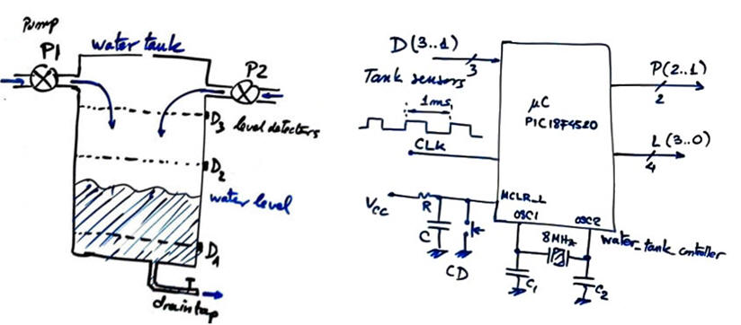
Water tank controller (μC - C) |
|||
|
|
|||||
1. Specifications
We want to design a water tank controller (Water_tank_controller) as an FSM using a microcontroller PIC18F4520 that can drive two pumps independently, as represented in Fig. 1.
The same project designed using hardware is stated in D2.9.
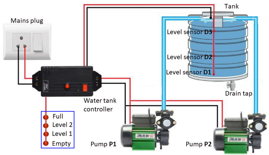
The tank has level sensors D1, D2, and D3 attached to the wall, so that a '1' is generated when the sensor is sunk into water. The controller works as follows: when the tank is empty, below D1, both pumps work simultaneously; when the water level is above D2 pump P1 stops; when the water is above D3, meaning that the tank is full, pump P2 stops; and finally, the pumps do not switch on until the water level is again below D1.
 |
|
Fig. 1. Diagram of the water tank installation. |
In addition to controlling the water level, we also want to indicate in a LED column the current level of the water in the tank.
Design phase #1. Example of design sequence to follow for completing the project.
a) Represent the Water_tank_controller symbol and details. We well use a 1 kHz CLK signal to run the FSM.
 |
|
Fig. 2. Tank sketch and symbol. |
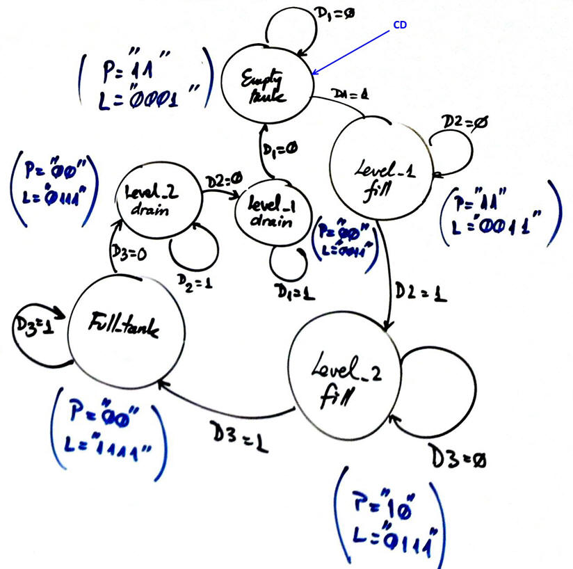
b) Adapt the state diagram from D2.9 to this problem. Consider RAM variables and deduce which signals will be read and which will generate interrupts. Indicate the required RAM variables.
c) Draw an example of timing diagram.
d) Draw the hardware schematic. Switches and resistors to represent sensors. LED to represent pumps and also the water level. Reset circuit MCLR_L and an 8 MHz quartz crystal oscillator. External CLK oscillator block. Which pins will interrupt? Which will be read? Assign inputs and outputs to μC port pins.
e) Draw the software flowchart organised as a FSM.
f) Draw the hardware/software diagram explaining how the FSM is solved in software.
g) Explain how to configure input and output pins and interrupts in init_system().
h) Draw the truth tables and their equivalent flowcharts for state_logic() and output_logic() functions.
i) What is the interrupt service routine ISR() used in this application? Draw its flowchart.
j) Develop and test (debugging) the project capturing the hardware circuit in Proteus and writing the C source code. Do not start your hardware circuit and software source file from scratch, but copy and adapt from examples in LAB10 or P10.
Design phase #2:
Let us add an LCD display to this application. The idea is represent the water level and pump activity using ASCII characters and symbols.
k) Enhance the schematic from design phase #1 to include an LCD attached to port D as studied in tutorials.
l) Enhance the software and the source file to drive the LCD.
m) In this phase there is also the possibility of two design steps, such step #1: print ASCII text messages; step #2: print as well numbers from 1 to 4 to indicate tank level from empty to full.
Design phase #3:
The external CLK is replaced by the internal 8-bit TMR2 peripheral to generate interrupts (TMR2IF). In this way, we will save power consumption, reduce board footprint, and also free an external INT for other future applications.
n) Calculate TMR2 parameters required to generate a CLK of 1 kHz (var_CLK_flag period = 1 ms) to run the machine.
o) You can add other features, for instance, a 2 kHz sound wave for a buzzer to indicate an alarm on empty tank.
| Home Term 24/25-Q1 Contact Products Electronic devices and companies Software Books Magazines Instruments DEE Library EETAC DEEL |

|
|
| Web activa des de 09/2001, @ F. J. Robert, J. Jordana. Web editat amb Microsoft Expression Web 4. El contingut és un complement als materials d'estudi del curs Circuits i Sistemes Digitals disponibles al campus digital Atenea. Llicència:Reconeixement 4.0 Internacional de Creative Commons |