|
|
Bachelor's Degree in Telecommunications Systems and in Network Engineering |
|
|
|
Radix-2 synchronous counter modulo 12 using plan C2 |
Designing standard sequential circuits using components
| 1. Specifications | Planning | Developing | Test functional | Test gate-level | Prototype | Report |
Evidently, the specifications are the same for plan X and plan Y designs. Pictures Fig. 1, Fig.2 and Fig. 3 represent symbol, function table, timing diagram and also the state diagram.
The idea of counter truncation and expansion is explained in this L7.3 lecture.
| Specifications | 2. Planning | Developing | Test functional | Test gate-level | Prototype | Report |
Hierarchical design using multiple VHDL files and components. The idea is truncating a larger counter like Counter_mod16 that is used as a building block. Discuss how this circuit works in Fig. 12. Study it for instance in two separate design steps:
- Step #1: Up counter considering only the CE control signal)
- Step #2: Add the UD_L control signal and discuss what blocks and logic has to be included in the basic design from phase 1 so that it becomes the circuit in Fig. 12.
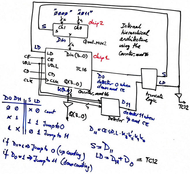 |
Fig. 12. Example of plan C2 circuit: Counter_mod12 implemented using standard Counter_mod16 building block. |
This is your project location:
C:\CSD\P7\Counter_mod12C2\(files)
| Specifications | Planning | 3. Developing | Test functional | Test gate-level | Prototype | Report |
These are the top Counter_mod12.vhd , and component Quad_MUX_2.vhd. In this tutorial there is the Counter_mod16.
Choose a MAX II device EPM2210F324C3 and start a Quartus Prime project.
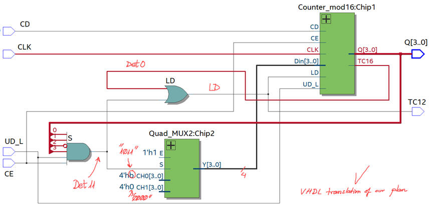 |
Fig. 13. RTL view translation of Fig. 12 schematic. |
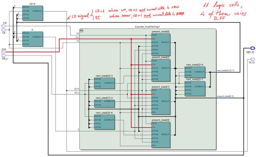 |
Fig. 14. Technology view schematic for a MAX II Intel CPLD. This plan C2 architecture is different from plan Y in Fig. 9, thus it will produce different propagation times. |
| Specifications | Planning | Developing | 4. Test functional | Test gate-level | Prototype | Report |
Running ModelSim and using the same testbench in Fig. 10 Counter_mod12_tb.vhd generates waveforms as in Fig. 11.
| Specifications | Planning | Developing | Test functional | 5. Test gate-level | Prototype | Report |
Gate-level simulations in ModelSim
Here is interesting to measure propagation times because we are proposing an alternative architecture that may be faster or slower than the one from plan X or plan Y.
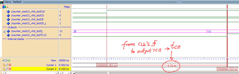 |
Fig. 15. Timing analyser spreadsheet for measuring tCO. |
Quartus Prime timing analyser
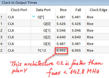 |
Fig. 16. Timing analyser spreadsheet for measuring tCO. |
| Specifications | Planning | Developing | Test functional | Test gate-level | 6. Prototype | Report |
| Prototype specifications | Planning | Development and Test & Measurements |
We can test and measure the counter characteristics in the laboratory building a prototype. This may be another demonstration on using the DE10-Lite board from Terasic, similarly as we did in LAB6 or in LAB4_2.
A similar prototype for the MachXO USB Starter Kit is proposed in this page Annex 1.
We can place in the same FPGA other auxiliary circuits to better observe how the counter behaves. For example, we can prepare two frequencies from the CLK_Generator for counting at different speeds. We can select whether to use internal waveforms or pulses form an external push-button. And, because the push-buttons are noisy devices, we can see which is the effect of using a debouncing filter for cleaning such signal. Therefore, from the sketch in Fig. 1 we will design a new Counter_mod12_top project adapted to the specific FPGA board.
|
|
|
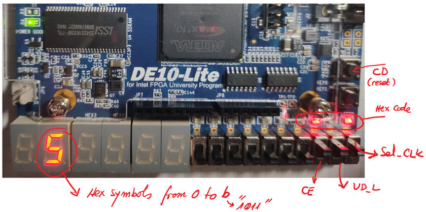
Fig. 1. Prototype sketch for testing how the counter operates. |
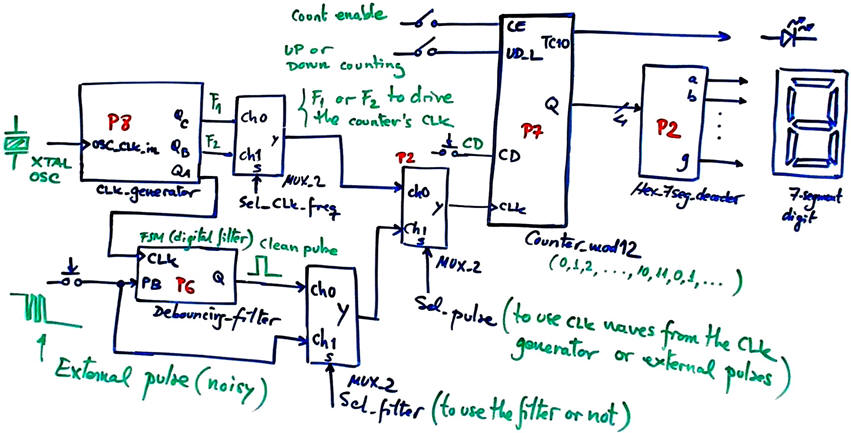
| Prototype specifications | Planning | Development and Test & Measurements |
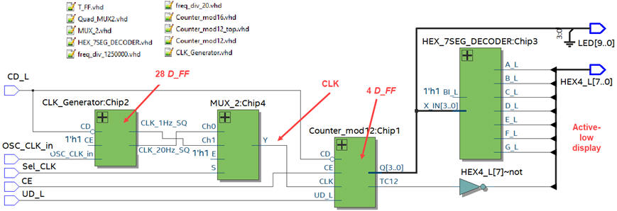
This time we can run the counter from two CLK signals of 1 Hz and 20 Hz using the Chip 4 MUX_2 as represented in the Counter_mod12_top design in Fig. 2. Sel_CLK will select one of the two CLK sources provided by the CLK generator. We can represent the binary code Q(3..0) also in a 7-segment display. We have to synthesise the project for the MAX10 target chip 10M50DAF484C7 installed in DE10-Lite board.
|
|
|
Fig. 2. Adapting the Counter_mod12 to the DE10-Lite board. Unused LED available on the board will be switch off. A new project Counter_mod12_top includes the additional blocks for generating the required CLK and control signals and interfacing the hardware. |
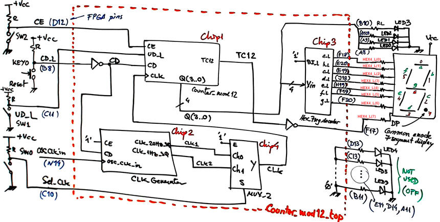
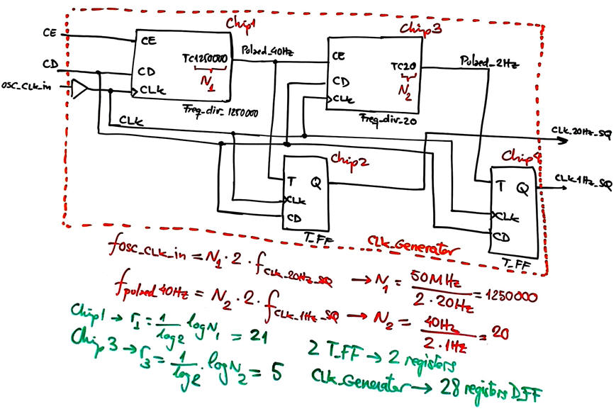
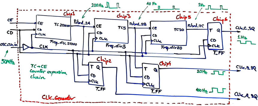
Fig. 3 shows the CLK_Generator.vhd schematic build using three internal components: Freq_div_1250000.vhd, Freq_div_20.vhd and T_FF adapting the chainable modular architecture discussed in L8.2.
|
|
|
Fig. 3. Internal architecture of the CLK_Generator. |
This time, the Hex_7seg_decoder is used to show the counter's current count in one of the 7-segment active-low displays (HEX4_L). And four active-high LED(3..0) to show hexadecimal numbers from 0 to B are also included.
Using the "MUX_2.vhd" found in P2, we can complete the translation into VHDL of the top schematic in Fig. 2 as "Counter_mod12_top.vhd".
Project location:
C:\CSD\P7\Counter_mod12_top\(files)
| Prototype specifications | Planning | Development and Test & Measurements |
1. Synthesis
And inspect the RTL to check that everything is in place. The number of D_FF registers used in this application is 28 + 4 = 32.
|
|
|
Fig. 4. RTL view and list of VHDL files included in the project. |
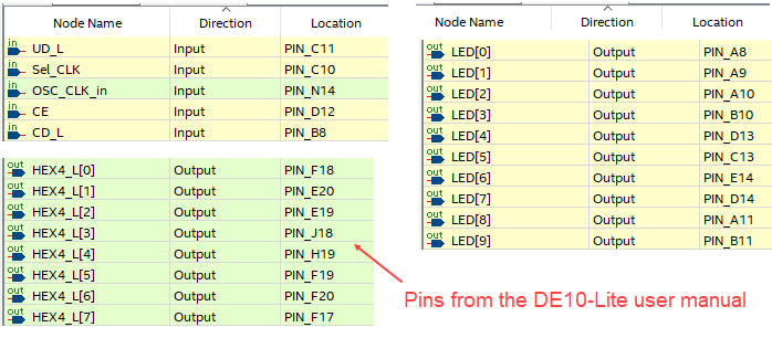
2. Pin assignment
Pin planner tools in Quartus Prime allows you to fix LED, switches and 7-segment displays.
|
|
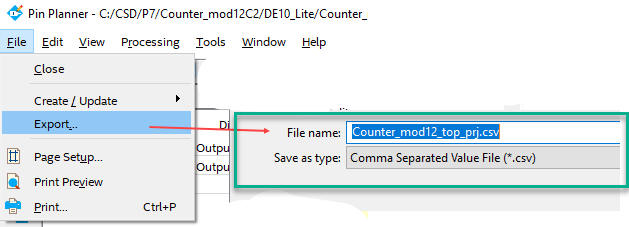
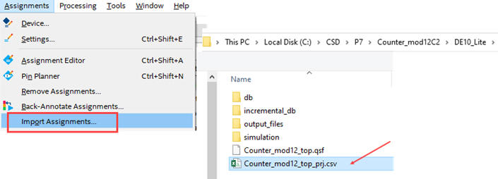
Fig. 5. Pin assignment list. It can be exported and imported using spreadsheet file extension."Counter_mod12_top_prj.csv". |
3. Programming
Programming the chip allows you to run the prototype with the current design. Check that the counter counts up, down or is disabled. Check that it can work at any of the two CLK frequencies.
|
|
|
Fig. 6. Picture of the final prototype running the application. |
This is the final Counter_mod12_top.sof file to configure the FPGA using the programmer. This is the list of VHDL files Counter_mod12_top.zip included in this prototype.
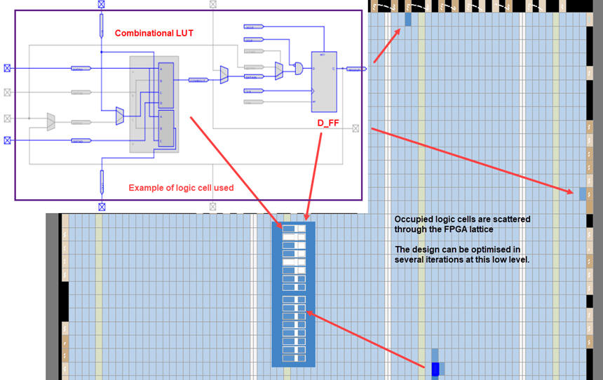
It is also a good opportunity to observe where are located in the FPGA the logic cells used in this application. We can open the Quartus Prime Chip Planner tool as shown in Fig. 7.
|
|
|
Fig. 7. Chip Planner showing the location of some of the logic cells synthesising the circuit. |
Optional: Experiment with noisy push-button signals and learn how the Debouncing_filter FSM can generate clean digital pulses. Add switches and other MUX_2 to the above prototype to allow you to input CLK pulses manually using the KEY1 when selected.
Chip 2 will be modified to generate another convenient square wave: 100 Hz for sampling the push-button KEY1. Sel_pulse switch will select internal CLK waveforms as in the first prototype or external pulses. Sel_filter switch will select between the raw external pulse version or the debounced one.
|
|
|
Fig. 8. The modified Counter_12_top to allow single manual clicks from KEY1 push-button. |
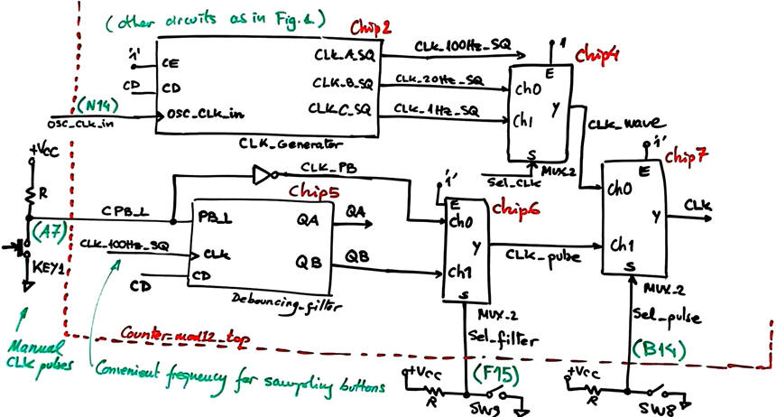
Fig . 9 shows how the Chip2 CLK_Generator can be modified to generate the additional 100 Hz square signal for running the Debouncing_filter Chip5 that will sample the KEY1 push-button.
|
|
|
Fig. 9. The modified CLK_Generator to include the 100 Hz CLK for sampling the CLK's button using the Debouncing_filter FSM. |
Synthesise again the project Counter_mod12_top at this new location:
C:\CSD\P7\Counter_mod12_top _pulse\(files)
This Counter_mod12_top.zip contains the new set of files to be included in the project. Or, instead, you can upload directly the "Counter_mod12_top.sof" or "Counter_mod12_top.pof" to the DE10-Lite using the Programmer app and experiment with the circuit.
|
|
|
Fig. 10. Experiment running considering the option to filter manual CLK pulses from the KEY1 push-button. |

| Specifications | Planning | Developing | Test functional | Test gate-level | Prototype | 7. Report |
Follow this rubric for writing reports.
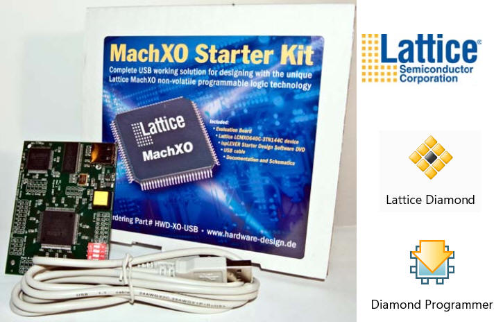
Annex 1: MachXO starter kit prototype
| Prototype specifications | Planning | Development and Test & Measurements |
Alternatively, we can use Lattice Diamond synthesis software and its embedded programmer to synthesise and upload the experiment on the Counter_mod12 in a MachXO USB starter kit board populated with the FPGA LCMXO640C-3TN144, after providing the necessary adaptations.
|
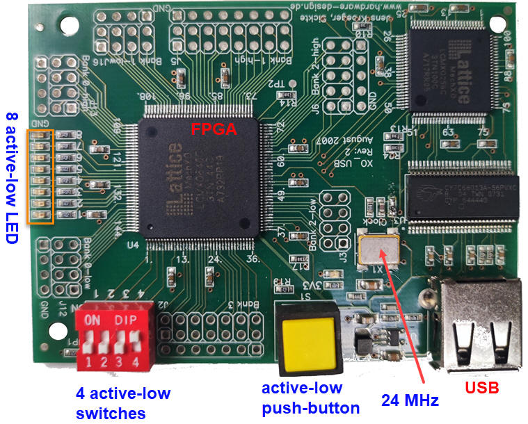
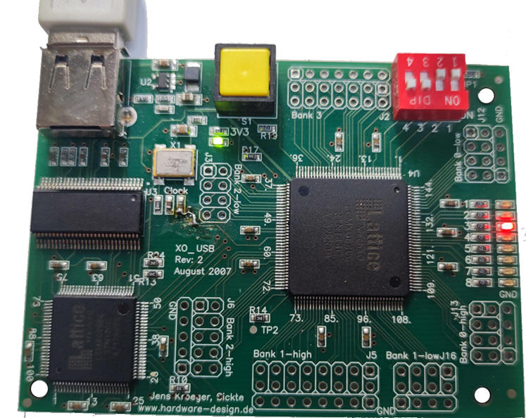
Fig. 1. MachXO USB Starter Kit populated with an FPGA LCMXO640C-3TN144 from Lattice Semiconductor. |
|
Fig. 2. MachXO USB Starter Kit populated with an FPGA LCMXO640C-3TN144 from Lattice Semiconductor. |
| Prototype specifications | Planning | Development and Test & Measurements |
Because only four switches are soldered in the board, we will imagine that CE = '1', UD_L = '1'.
|
|
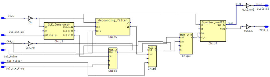
Fig. 3. Modified Counter_mod12_top project allowing single pulses from a push-button. |
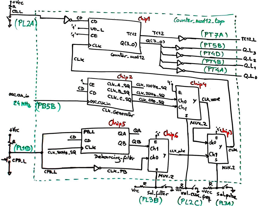
We can as well modify the top circuit to play also with the debouncing filter. A switch Sel_filter will connect the debouncing filter or instead will attach the external push-button directly to the counter CLK.
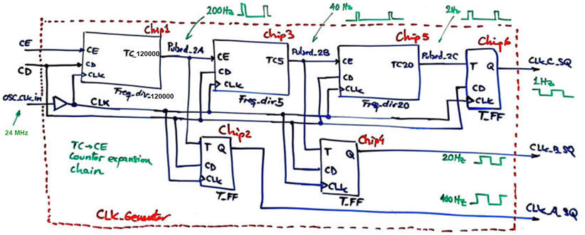
In this board the crystal quartz oscillator is 24 MHz, thus N1 = 24000000/200 = 120000. We have to replace the previous Freq_div_250000 by the new Freq_div_120000 to obtain the same squared waveforms as shown in Fig. 4.
|
|
Fig. 3. The modified CLK_Generator to adapt the 24 MHz crystal oscillator. |
Project location:
C:\CSD\P7\Counter_mod12_MachXO\(files)
| Prototype specifications | Planning | Development and Test & Measurements |
1. Synthesis
We have to start a synthesis project in Lattice Diamond. You can ask for a free one year licence to install this software in your portable.
|
|
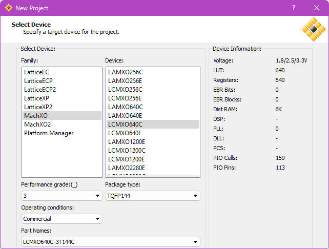
Fig. 5. Selecting the target chip. |
The RTL view is copied in Fig. 6.
|
|
Fig. 6. RTL view. |
2. Pin assignment
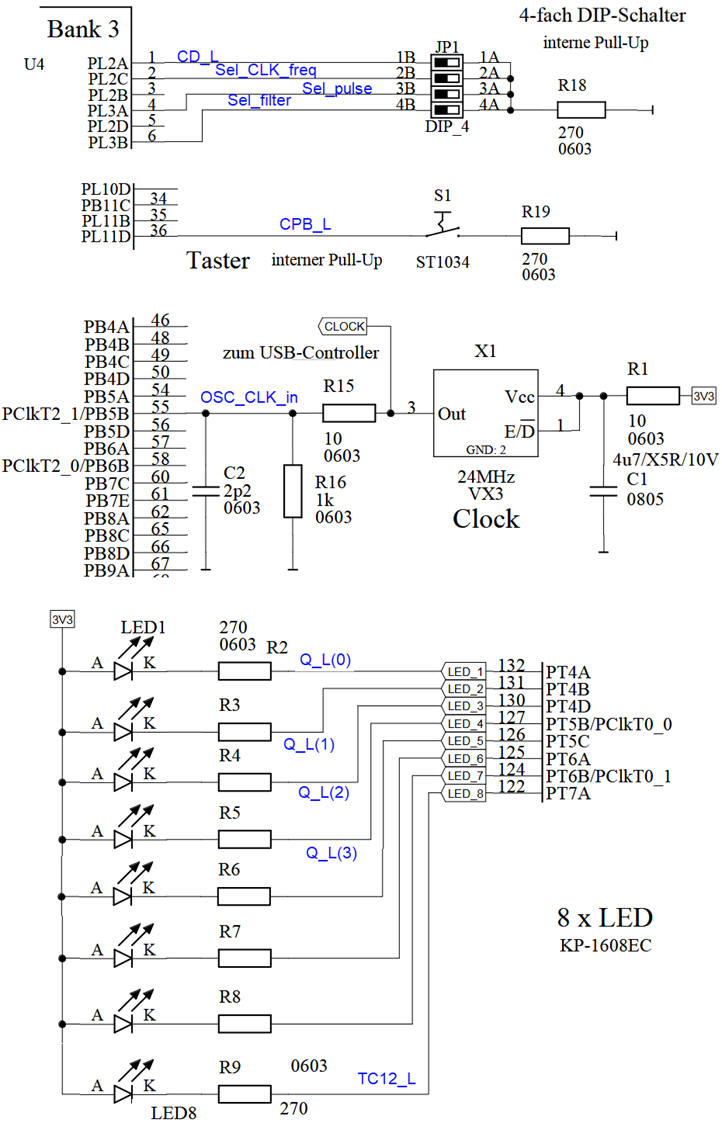
Paying attention to the board's schematic we will select input and output pins for this application.
|
|
Fig. 7. Pin assignment. |
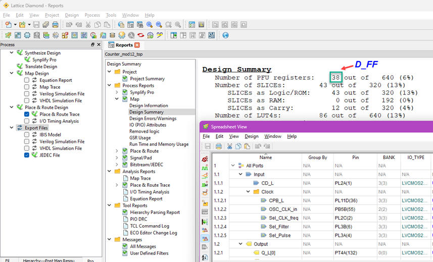
This circuit uses 38 D_FF.
3. Programming the FPGA
|
|
Fig. 6. Circuit running the application. |
And the final prototype running picture is in Fig. 8.
|
|
Fig. 6. Circuit running the application. |
Is the Debouncing_filter effective 100% or there is still some random signal bouncing that affects counting? How to make the circuit more reliable?
This Counter_mod12_top.zip contains the new set of files to be included in this Lattice Diamond project. You can upload directly Counter_mod12_top.jed to the Starter kit using the standard alone programmer application.
Optional: Once plans X, Y and C2 are comprehended running these examples or similar ones, you may like to try inventing other counters and registers applying plan Y and plan C2 using our components Counter_mod16 (type 74ALS169) and Shift_reg_4bit (type 74HC194HC194).
The highlighted project Hour_counter in P7 on a counter modulo 24 for counting hours is an example where we apply plan C2 techniques like truncating the count to obtain 24 states from a modulo 100 2-digit BCD counter.
| Home Term 26/27-Q1 Contact Products Electronic devices and companies Software Books Magazines Instruments DEE Library EETAC DEEL |

|
|
| Web activa des de 09/2001, @ F. J. Robert, Web editat amb Microsoft Expression Web 4. El contingut és un complement als materials d'estudi del curs Circuits i Sistemes Digitals disponibles al campus digital Atenea. Llicència:Reconeixement 4.0 Internacional de Creative Commons |