|
|
Bachelor's Degree in Telecommunications Systems and in Network Engineering |
|
Lecture 2 |
L8.2: CLK generator design [P8] CLK Generator / timer circuits / applications |
[20 Nov] |
2.8.4. CLK_Generator circuit
2.8.4.1. Frequency divider circuit
Let's build an example of synchronous CLK_Generator circuit to provide all CLK signals required by a given application. Let us imagine three outputs.
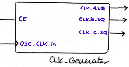 |
Fig. 1. Example entity. Outputs are synchronous with OSC_CLK_in and squared (50% duty cycle waveforms).
The idea is CLK frequency division, where NA is a natural number: FCLK_A_SQ = FOSC_CLK_in/NA |
The strategy will be using plan C2 consisting of a series of cascaded frequency dividers (Freq_div_Mod) to obtain the pulsed signals and then using T_FF to produce the required squared outputs from the pulsed signals. Generally, for common applications, the initial OSC_CLK_in to which all the derived signals are synchronised is a high frequency crystal oscillator.
The idea of dividing frequency by a number N is represented in Fig. 2. Imagine the Counter_mod12 at Lab7 designed using plan Y. If our interest is on the output TC12 and not on the binary code, we can imagine a frequency divider by 12 with a rectangular waveform shape of a duty cycle DC = TON/TTC12 = 8.3%.
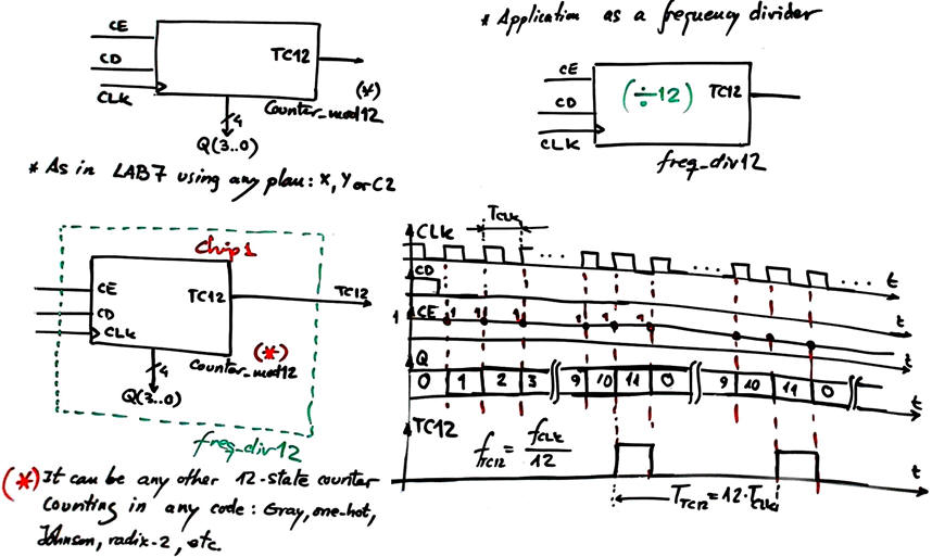 |
| Fig. 2. The frequency divider circuit concept. For instance, if the input is fCLK = 1.2 kHz , the circuit divides by 12 generating an output fTC12 = 100 Hz synchronous rectangular output signal. |
2.8.4.2. Pulsed to square waveform converter using T_FF
The next idea is that we can chain the Freq_div12 to a T_FF to solve the problem of squaring inconvenient pulsed waveforms. The cost is dividing again by 2.
The frequency divider modulo NA can be any number. Consider for instance, NA = 25000000. An external oscillator OSC_CLK_in = 50 MHz will generate an internal Pulsed_2A with a frequency of 2 Hz; its '1' pulse duration will be TOSC_CLK_in = 20 ns. However, the CLK_Generator output will be a squared signal CLK_A_SQ of 1 Hz frequency.
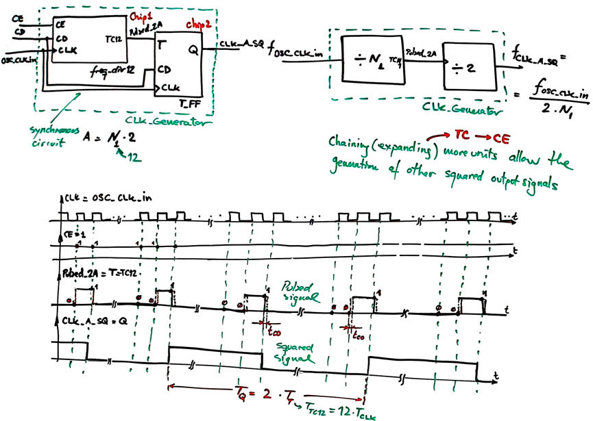 |
| Fig. 3. The concept of CLK_Generator. NA = 2·N1 |
2.8.4.3. Adaptable generic structure
Thus, the generic plan C2 architecture for the CLK_Generator is represented in Fig. 4
 |
| Fig. 3. The concept of CLK_Generator. NA = 2·N1; NB = 2·N2; NC = 2·N3. OSC_CLK_in = N1·2·CLK_A_SQ = N1·N2·2·CLK_B_SQ = N1·N2·N3·2·CLK_C_SQ |
This CLK_Generator is a complete project to show you how to generate up to four synchronous square waves at: 100 kHz, 1.6 kHz, 20 Hz and 1 Hz. It is used as the Chip3 in the highlighted programmable P8 Timer_MMSS application.
Other features on CLK generators circuits: How to generate a programmable frequency divider?
Activity #1: We have to design a CLK_Generator circuit to obtain from a 36 MHz crystal oscillator up to three standard RS232 transmission frequencies or baud rates (bits per second): 28.8 kb/s, 1.8k b/s, 75 b/s. We will use plan C2 and the circuit proposed in Fig. 4.
- Calculate the required frequency divider ratios N1, N2 and N3.
- Determine the number of D_FF required and also the number of VDHL files to be include in this project.
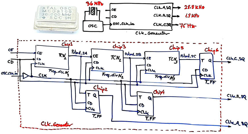 |
| Fig. 4. Generating several standard RS232 transmission frequencies. See the basics of a serial transmission in this project P10. |
Optional on CLK generators circuits: How to generate any frequency from an standard quartz crystal oscillator? How to generate all the standard transmission frequencies available in an USART serial port?
Optional on advanced ideas on PLL (phase-locked loop) circuits used as CLK multipliers. How to generate output frequencies higher that the oscillator CLK? This ICS501A from Renesas or CDCEx937 from Texas Instruments are examples of PLL based CLK multipliers.
How to generate fractional frequencies and the generalised concept of frequency synthesiser?
2.8.5. Examples and applications of dedicated processors
2.8.5.1. MM:SS timer (P8) {Timer_MMSS}
2.8.5.1.1. The basic idea of an R-C timer circuit
The same strategy on charging and discharging capacitors by means of switching networks (logic gates or integrated circuits) is applied in this unit on timer circuits.
2.8.5.1.2. RC timer and re-triggerable functionality
2.8.5.1.3. Integrated circuit 555 timer
Optional advanced concepts. This is where our CSD introductory course on hardware design and VHDL ends. This is where an advanced course on digital circuit design should start: the concept of intellectual property (IP), the key to design tailored professional applications targeted to commercial chips.
- Example paper by Okahara, A; Miwa, S.; Kimura, S..
- Framework paper on "The future of semiconductor intellectual property architectural blocks in Europe" link.
- Example of RAM block using intellectual property component libraries.
Another flow from a book explaining the design concept that we have tried to put into practice in our projects.
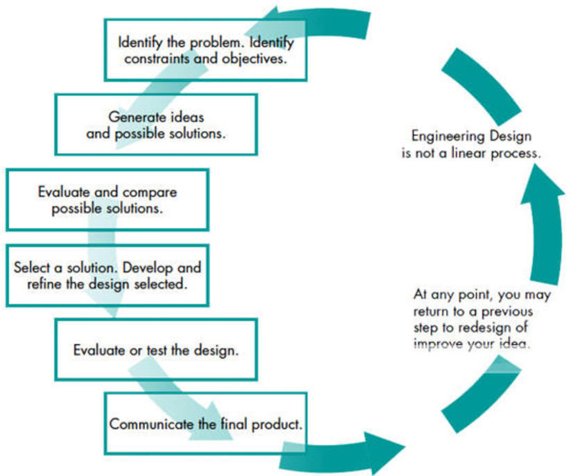 |
| Fig. 6. Typical design cycle in engineering. |
Up to this point in the course, you have learned what represents the basics of hardware design of modern digital systems. No doubt that you can continue this subject's content designing with hardware tools and VHDL advanced systems and even microprocessors and microcontrollers. This is the path proposed in most of the introductory books on digital systems. However, the next Chapter 3 for our CSD course will be based on the use of a commercial microcontroller, precisely for repeating some previous projects from the software point of view.
| Home Term 26/27-Q1 Contact Products Electronic devices and companies Software Books Magazines Instruments DEE Library EETAC DEEL |

|
|
| Web activa des de 09/2001, @ F. J. Robert, Web editat amb Microsoft Expression Web 4. El contingut és un complement als materials d'estudi del curs Circuits i Sistemes Digitals disponibles al campus digital Atenea. Llicència:Reconeixement 4.0 Internacional de Creative Commons |