|
|
Bachelor's Degree in Telecommunications Systems and in Network Engineering |
|
L7.3: Counter truncation; counter and register expansion [P7] Count truncation (plan C2). Chaining counters and registers (plan C2). |
[17 Nov] |
2.7.4. Count truncation and count expansion
2.7.4.1. Concepts and chaining signals
2.7.4.2. Design plan C2: designing counters using hierarchical structures, standard components (Counter_mod16) and logic, VHDL hierarchical multiple-file project
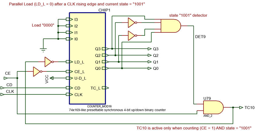
2.7.4.2.2. Example of count truncation: Decade counter (10 states) or Counter_BCD_1digit
- Design: Counter_BCD_1digit using plan C2 and a Counter_mod16 as component.
Other count truncation examples:
- Design the Counter_mod12 using plan C2 and a Counter_mod16 as component (LAB7)
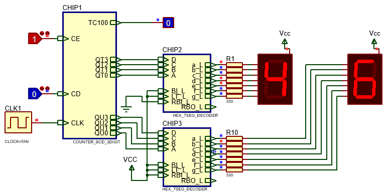
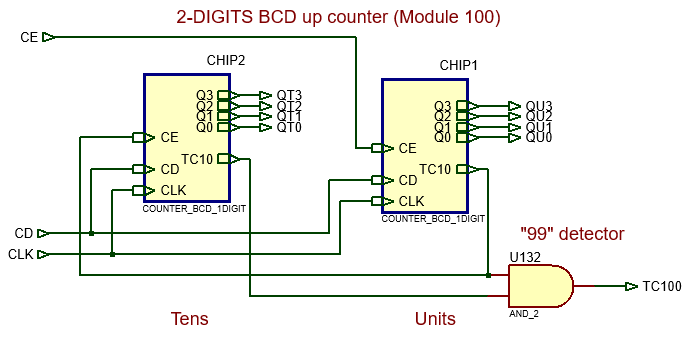
2.7.4.2.3. Example of count expansion: 2-digit BCD counter (modulo 100)
Count expansion. Let us discuss about the concept of counter or register expansion (chaining/rippling). In this way you can design a counter or a register of any size using plan C2 and building blocks. This is a Counter_BCD_2digit in Proteus.
2.7.4.2.4. Example of count truncation and expansion: Counter_BCD_mod60
Count expansion and truncation
- Design a Counter_BCD_mod60 (minutes or seconds counter) using plan C2 and a Counter_mod16 as component.
2.7.4.2.5. Example of count expansion: Hour_counter (Counter_BCD_mod24)
- Design an Hour_counter (or Counter_BCD_mod24) using plan C2 and a Counter_mod16 as component.
How to plan a typical YY-MM-DD HH:MM:SS calendar watch? This DS1307 chip is an example of real-time calendar. How many bits are necessary for implementing a 100 years calendar (counting in BCD, counting in binary sequential)?
How to invent a BCD counter modulo 10.000.000 using Counter_BCD_1digit components? For instance, this is a professional frequency/period meter instrument that includes such large counter.
Invent a reversible Counter_mod128 with adjustable count between Min_count and Max_count. For instance if CE = '1', UD_L = '0', Min_count = 40; Max_count = 50, the device will generate the following eleven state sequence: 50, 49, 48, ..., 41, 40, 50, 49, ...
You may think on the following plan based on several steps: (1) invent a Counter_mod128 with parallel inputs, using plan Y or using plan C2 including two Counter_mod16. (2) Discuss a plan C2 schematic on how to make it adjustable between Min_count and Max_count using standard components such multiplexers and comparators.
Data register expansion.
- Invent a Data_reg_16bit using Data_reg_4bit components and plan C2.
Compare the solution with the design of a Data_reg_16bit using plan Y.
Shift register expansion.
- Invent a Shift_reg_12bit using Shift_reg_4bit components and plan C2.
Compare the solution with the design of a Shift_reg_12bit using plan Y.
Activity #1: Invent a Shift_reg_10bit using Shift_reg_4bit components and plan C2. How many VHDL files are required?
Compare the solution with the design of a Shift_reg_10bit using plan Y. How many VHDL files are required?
Which plan uses more resources (logic elements and D_FF)?
Activity #2: Invent a Counter_mod38 using Counter_mod16 components and plan C2.
Even if we are discussing planning strategies, you have to start your activity by explaining the circuit specifications. We are working with this concept map in mind.
In a first phase, you can consider counting in one direction: up or down. In a second phase, drawing on prior experience, you can add directionality via the UD_L control signal.
Additionally, plan the schematic in two steps:
#1: study how to expand up to 8-bit modulo 256 (design a Counter_mod256)
#2: truncate at the 37th state. Discuss how to modify your first circuit so that it will now become a Counter_mod38.
How many VHDL files are required? Which? How many D_FF will the circuit contain?
Compare the same Counter_mod38 solved using plan Y. How many VHDL files are required? Which? How many D_FF will the circuit contain?
Optional as class activity (only if you have study time available to spare on it). Synthesise and test the circuit for the first phase step #1. NOTE You can not develop VHDL files unless you have a plan C2 perfectly annotated schematic ready for translation. Draw your testbench schematic before testing your circuit functionally.
Activity #3: Invent a Counter_mod100 using Counter_mod16 components and plan C2 that down counts in radix from 199 to 100. Thus the output codes are is 199, 198, 197, ..., 102, 101, 100, 199, 198, ... How to implement the CD so that when clicked, the counter goes asynchronously to the initial state 199?
| Home Term 26/27-Q1 Contact Products Electronic devices and companies Software Books Magazines Instruments DEE Library EETAC DEEL |

|
|
| Web activa des de 09/2001, @ F. J. Robert, Web editat amb Microsoft Expression Web 4. El contingut és un complement als materials d'estudi del curs Circuits i Sistemes Digitals disponibles al campus digital Atenea. Llicència:Reconeixement 4.0 Internacional de Creative Commons |