|
|
Bachelor's Degree in Telecommunications Systems and in Network Engineering |
|
2021Q1 - List of preparatory laboratory assignments (PLA), projects and questionnaires
NOTE: VHDL EDA in use: Intel Quartus Prime Lite, ModelSim Intel Edition, Proteus electrical simulator (to be used only at VD), minilog minimiser, notepad++ editor, Microchip MPLABX and XC8 compiler.
PLA1 analysis and design of logic circuit
Assigment. Analyse Circuit_T and design equivalents Circuit_2 and Circuit_4. Due date: October 9.
PLA2 Designing a standard logic circuit 74185A (structural plan A and behavioural plan B).
6-bit binary to binary-coded decimal (BCD) onverter. Assigment. Due date: October 23. Extended due date: October 25, 18:00.
Studying 74185A features described in its datasheet, we have decided this adaptation: symbol and truth table to organise our Bin_BCD_converter_6bit. In this way we have a new CSD component to be included in other projects when necessary, the same we did for the 74LS47 that now has become our HEX_7seg_decoder and many other classic chips.
Questionaire Q1_2 by October 27
PLA3_4 on the design of arithmetic circuits and hierarchical design (plan C2). Propagation time measurement and circuit's speed calculation.
9-bit integer adder/subtractor with 7segment outputs. Assigment. Due date: November 7
This is about three projects to design internal components Chip1, Chip2 (that includes itself also another Chip2 as component) and Chip 3,4,5), and then the forth project plan to design the top entity symbol (Int_Add_Subt_9bit_7seg).
We recomend you to work in cooperation, use your lab chat rooms, use example input data in each chip to figure out the way circuits work and how they combine in such way for processing numbers. Think ahead how to proceed and be sure to count how many VHDL files you need for each component, for instance:
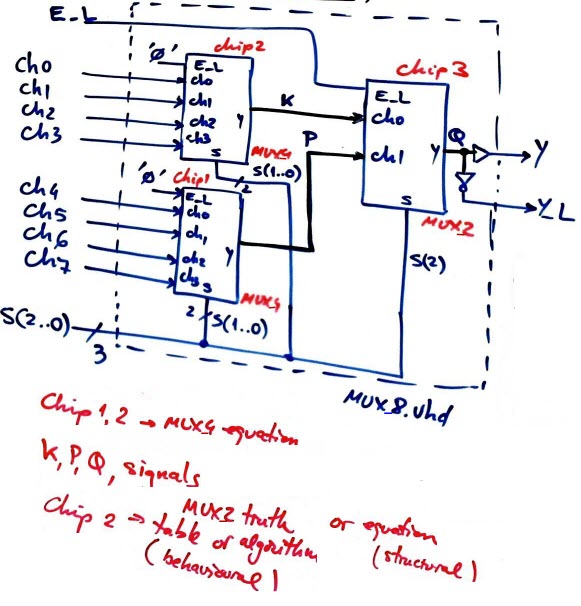
----> STARTING POINT: Run LAB#4 tutorials in group. Run the two tutorials MUX_8 and Adder_4bit. Pay all the attention on how such top entities (MUX_8 plan) are translated to VHDL (MUX_8.vhd). Do NOT go anywhere else unless these translations, the key of plan C2, are fully understood. Imagine that the file MUX_8.vhd is not given to you and you have write it from the structure.
- Solve completely Chip 1 ---> 1 --> 2 --> 3 --> 4 (all the team members in group, and only after having run LAB#4 tutorials above)
- Solve completely Chip 2 --- > 1 --> 2 --> 3 --> 4
- Invent Chip3 (fig. 7) and ---> 1 --> 2 --> 3 --> 4
- Complete the top entity in Fig. 3
- Solve for any project the design step 5 (gate level simulation and timing analyser)
- Report one project at a time in a sequence. Realise that questions a, b, c and d in 1, refers to the top entity but similar questions may be answered to fully comprehend each component before planning and developing it. In this project there are four chips to design, you must draw symbols, truth tables and timing diagrams for each one of them before thinking of planning them.
Questionaire Q3_4 by November 3
|
|
PLA5_6 on 1-bit memory cells and FSM
Assigment Analysis of asynchronous circuits, designing functions using method of ROM, and designing applications based on FSM. Due date: Rescheduled due date: December 8 20:00
There are several synchronous and asynchronous circuits in our problem collection (problems: 5.3, 5.4, 5.5, 5.8, and 5.9). Some of them have tutorial solutions. And this a Proteus circuit to play with flop-flops as if we were in the laboratory building such circuits for real using the classic 4000 CMOS series (when picking parts from the library to mount your circuit, do this initialization --> Tool--> global annotation --> total) .
This is a discussion on traffic light specificactions taken from our former tutorial with some modifications. Only phase 1 is implemented in this PLA: no pedestrian buttons and no vehicle detectors. The programmable light timer in charge of counting real time is placed as an external circuit, thus LT_flag is an external input LT. The same for the 2 Hz yellow oscillator for night mode of operation, it is an external circuit that drives Yosc. These external circuits will be invented later in other projects.
- Ideas on traffic light controllers (1), (2) from web pages. We implement the UK traffic light sequence without dead periods.
- The state diagram proosed is practically the same one from the tutorial.
- The VHDL testbench fixture to verify that your design phase 1 for the Traffic_light_controller works correctly.
Questionaire Q5_6 by November 24
Questionaire Q7-8 by December 15
Final P_Ch3, report + oral presentation
For instance let us design a stopwatch. Assigment. Due date: January 15 20:00
These are some notes for organising the way to start. As the one drawn in Fig. 3, this is yet another way to infer a state diagram for Project 1.
Here you have two examples (1) and (2) on how to format dynamic data for the LCD in Project 3.
Remember that here you have examples of projects from former courses, and here indications on oral presentations.
|
Happy new year! Now, many students are asking questions about how to conceive and start P_Ch3. These are some general guidelines:
All the projects here in CSD are conceived the same. And
when a large project is subdivided in smaller projects, you
can solve it easier. And you have examples in P9, P10, P11
and P12. 1. Specifications/theory. Symbol, timing diagram, features. 2. Planning. Try to infer the circuit as if it were in P6-P7-P8. This is where and how you conceive the circuit, even if later you adapt and "program" it in C. Besides, in this way you study P5-P6-P7 and P8 at the same time. Again, as from P1 to P8, it is drawing and inventing hardware circuits, not programming as in the traditional sense. In some way, we do not program but simply write circuits in C instead of VHDL).
2.1. Hardware circuit. 3. Development and 4. Test (--> translate (using sample files to copy and adapt) all the planned materials to Proteus and to C, and compile and run & debug interactively with both windows opened) ===> Never try 3 & 4 without having completed 1 and 2 in paper. It is a waste of time and it will not be marked. Use your sketches in paper and not your C code to discuss in group because everything that you translate to C exists before as a flowchart. ===> Never try Project 2 v1 without finishing successfully 1-2-3-4 for the Project 1. ===> All group members have to work and stydy in parellel solving the same Project 1, then all the group members will work together again in parallel to solve Project 2 v1, and so on. This is the only way to be sure that anyone of you can solve exams and questionnaries. Before attempting Project 1 in the P_Ch3. Study/discuss/analyse in detail example circuits, for instance the 4-bit serial transmitter in P10, or the Timer in P12. Take this P_Ch3 not as something apart but just another exercise as the many others in CSD, as an incentive and motivation to study materials from P1 ... P12 for questionnaires and exams. |
|
Some additional comments on the last part of P_Ch3: - Because of the many counters in the datapath, perhaps you find easier designing such devices using P10 Plan Y adaptation, this is inventing counters for a large number of states. - Because writing to LCD takes time (it is a slow peripheral), writing when counting to represent the current real-time value, will generate a systematic error (one second is not exactly one second). However, real-time is possible when trying optional Project 5 on replacing external CLK by internal TMR. This is a topic we'll discuss in class/lab. This examples show how to use TMR0 (1) (2) and TMR2. |
Take a look at this newspaper information on intermittent lights for bikes (January 10, 2021), TICC Barcelona. It is about blinking LEDs, isn't it?, even Project 1 can be of industrial interest. Imagine specifications for such design: bike direction sensors, movement sensors, connections to your mobile phone, GPS, renewable power supply, bike lanes maps, etc. It is all about creativity.
Questionaire Q9_12 by January 12
Other similar projects and PLA from former courses
- 1921Q1
- 1920Q2
- Project list and some ideas on how to organise and assess oral presentations and written reports for project P_Ch3.
| Home Term 23/24-Q2 Contact Products Electronic devices and companies Software Books Magazines Instruments DEE Library EETAC DEEL |

|
|
| Web activa des de 09/2001, @ F. J. Robert, J. Jordana. Web editat amb Microsoft Expression Web 4. El contingut és un complement als materials d'estudi del curs Circuits i Sistemes Digitals disponibles al campus digital Atenea. Llicència:Reconeixement 4.0 Internacional de Creative Commons |