|
|
Bachelor's Degree in Telecommunications Systems and in Network Engineering |
|
|
|
Timer circuit. Phase #2: timer + LCD |
External peripherals
Design phases ==> #1: Timer ==> #2: Timer_LCD ==> #3: Timer_LCD_TMR0 ==> #4: Timer_LCD_TMR2
| 1. Specifications | Planning | Dev. & test | Prototype | report |
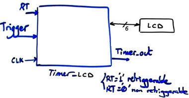
Design phase #2: Continue the design of the fixed-time Timer (for instance TP = 18.5 s) adding an LCD screen for representing information, ASCII messages (text and numerical data) on the screen. The symbol is represented in Fig. 1.
 |
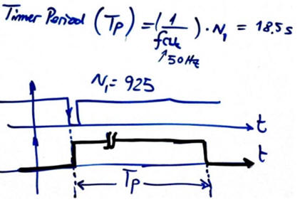 |
Fig. 1. The timer symbol and basic waveform in non-retriggerable mode of operation. |
|
Features:
- Same features as in design phase #1 Timer.
- Add the standard LCD kit type LM1602L with parallel interface.
- Organise the solution in two steps:
- Step #1 The information to write may be simple ASCII messages such "Hello World"
- Step #2 The information may include dynamic data such time in seconds while down-counting.
| Specifications | 2. Planning | Dev. & test | Prototype | report |
A) Planning hardware
The LCD interface is copied from the example in P11. D(7..4) for the 4-bit data bus, LCD_E to enable the chip, and LCD_RS to send instructions or data. If only writing to the device is required, the control signal R/W can be connected permanently low (RW_L = '0'), thus six port pins are necessary for this parallel interface.
|
|
|
Fig 3. LCD 4-bit parallel interface. |
In this way the hardware schematic is presented in Fig. 3.
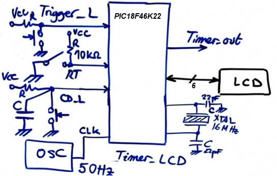 |
Fig. 3. Electronic circuit sketch. |
B) Planning software
Draw the hardware-software diagram. Discuss how the state diagram is modified to adapt the LCD. What new signals are required? What is var_LCD_flag?
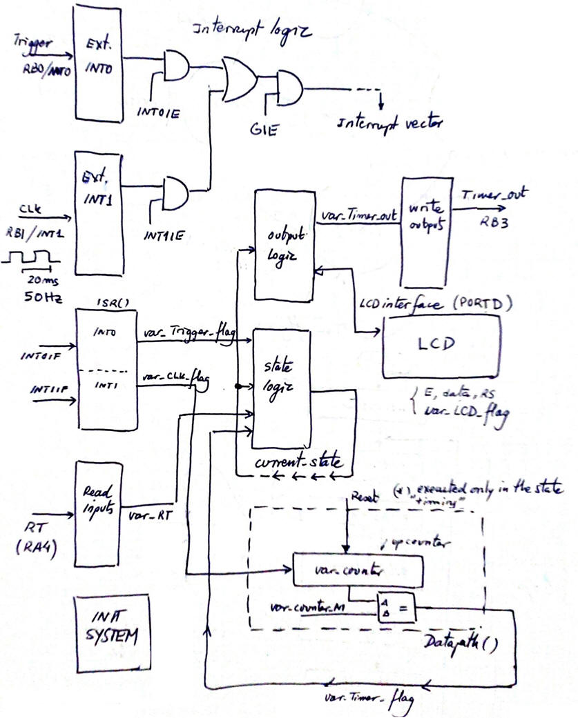 |
Fig. 4. Hardware-software diagram is the same as in design phase #1 adding the LCD interface connected to output_logic() function. |
Modify init_system() function.
 |
Fig. 5. Adaptations in init_system(). The configuration of the six PORTD pins to interface the LCD will be handled by the display library |
Modify state-logic() and output_logic(). Truth tables and flowcharts.
|
|
Fig. 6. Adaptations in state-logic() and output_logic(). |
Project location:
C:\CSD\P12\Timer_LCD\(files)
| Specifications | Planning | 3. Dev. & 4. test | Prototype | report |
We will start copying the previous files from design phase #1 in the new folder location changing their names. We will compile and run the simulations to check that everything works before adding the LCD code introducing and changing their names.
A) Developing hardware
Add the LCD display to the previous hardware from design phase #1. This is an example "Timer_LCD.pdsprj" hardware.
 |
Fig. 7. Circuit captured in Proteus. |
B) Developing software
The XC8 compiler version is v3.01 or newer, C standard is C99. And these LCD library files "lcd.c", "lcd.h" have to be included in the project. The file "config.h" contains all the microcontroller configuration bits. This is an example source file containing the LCD adaptations "Timer_LCD.c". Generate the executable (*.hex) and debugging files (*.cof).
C) Step-by-step testing
Fig. 8 shows the circuit running representing ASCII characters on the LCD screen.
 |
| Fig. 8. Timer with LCD running. |
The idea is for easy debugging, write, compile and run a bit of code with both windows working interactively: hardware Proteus environment and software IDE. Use the watch window, break points and step-by-step mode to stop and control the program execution and monitor RAM variables of interest for each function.
 |
|
Fig. 9. The timer running while watching the software main variables. |
| Specifications | Planning | Dev. & Test | 5. Prototype | Report |
Example 1: Board CSD_PICstick . Target microcontroller: PIC18F46K22. Tools: MPLAB X + XC8 + Proteus + VB8012 compact instrumentation.
For this first experiment we can connect the LCD through the 40-pin flat cable and the prototype board or only the six individual female-male wires.
| Specifications | Planning | Dev. & Test | Prototype | 6. Report |
Follow this rubric for writing reports.
Previous design phase #1: Timer.
Next design phase #3: Timer_LCD_TMR0.
| Home Term 26/27-Q1 Contact Products Electronic devices and companies Software Books Magazines Instruments DEE Library EETAC DEEL |

|
|
| Web activa des de 09/2001, @ F. J. Robert, Web editat amb Microsoft Expression Web 4. El contingut és un complement als materials d'estudi del curs Circuits i Sistemes Digitals disponibles al campus digital Atenea. Llicència:Reconeixement 4.0 Internacional de Creative Commons |