Legacy hardware: CPLD type ispMACH4128V |
| Prototype specifications | Planning | Development and Test & Measurements |
Let us adapt the Counter_BCD_mod60 to the complex programmable logic device CPLD ispMACH4128V from Lattice Semiconductor populating the JK_HWD4128V training board.
 |
|
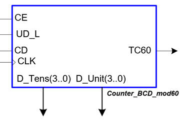
Fig. 1. Symbol of the basic counter. |
We will implement basic features explained in P6 - P7 - P8 on the top design, such:
We will add some additional features to the top design, such:
- Switch for selecting two CLK frequencies for fast (20 Hz) and slow (1 Hz) counting (Sel_CLK_freq)
- Count enable switch (CE)
- Switch for counting up or down (UD_L)
- Switch for selecting manual or internal oscillator CLK signal (Sel_pulse)
- Switch for selecting raw CLK input from the push-button (CBL_L) or debounced and filtered pulse (Sel_filter)
- TC60 LED indicator, terminal count, one pulse every 60 rising CLK edges.
- 8-bit LED array for representing the BCD codes of units and tens of the current count.
- Tens and units 7-segment displays to show the current counter count.
- LED ticking at 1 Hz (LED_CLK_1Hz_SQ)
- LED for indicating manual CLK (LED_CLK_pulse)
This is the time for reviewing the basic ideas on CPLD and study board resources like LED indicators, jumpers, switches, and push-buttons available for applications:
-Basics on CPLD.
- ispMACH4000 architecture. Number of macrocells available for experimentation.
- How to program CPLD devices using the *.jed file.
- JK HWD4128V board. Electronic schematic: switches, LED, push-buttons, etc. for determining which pins to assign to the application.
| Prototype specifications | Planning | Development and Test & Measurements |
We will follow the steps:
1. Develop and test functionally the application in Quartus Prime. Project folder:
C:\CSD\LEGACY\JK_HWD\Counter_BCD_mod60_top\(files)
2. Copy the project's VHDL source files in the Window 7 VM for resynthesising using ispLEVER Classic from lattice Semiconductor. Project folder in Windows 7:
C:\CSD\JK_HWD\Counter_BCD_mod60_top\(files)
3. Assign pins with the constraint editor and generate the configuration file *.jed.
4. Use the LSC ispVM System or the Lattice Diamond Programmer to configure the CPLD device and check you the application works.
The fully annotated plan C2 schematic in Fig. 2 is proposed for this adaptation to the FPGA board.
 |
|
Fig. 2. Counter_BCD_mod60_top adaptation. |
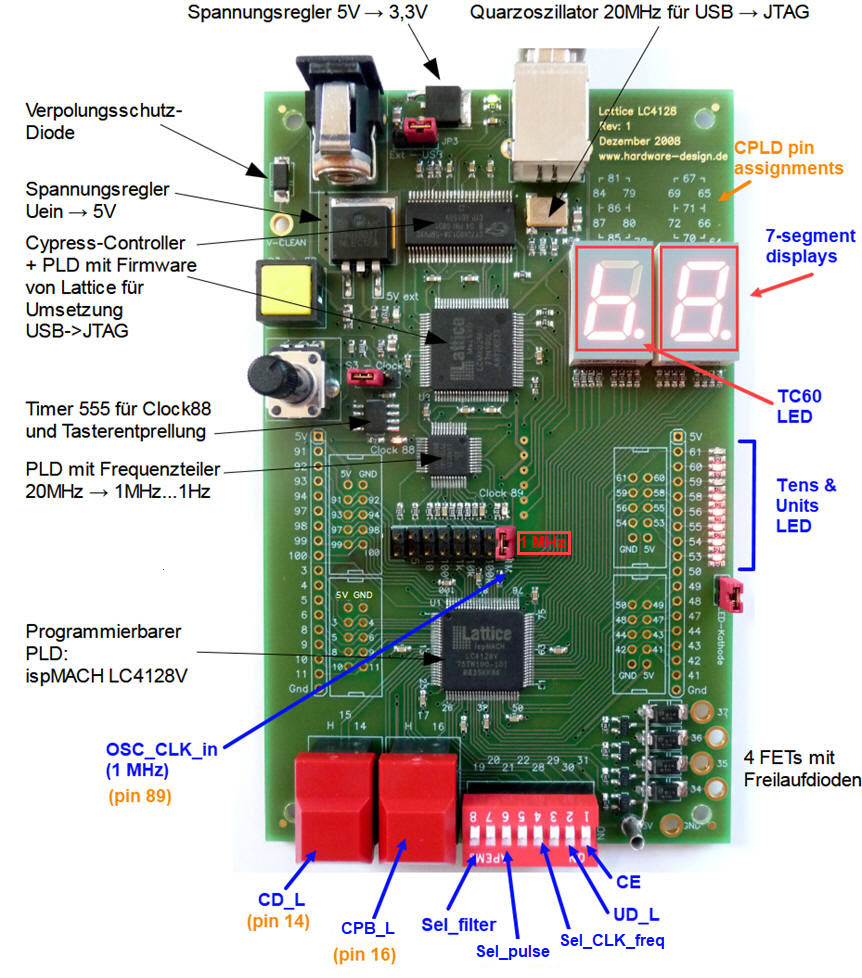
The JK HWD4128V training board contains enough resources for implementing this application.
 |
|
Fig. 3. Indication of the board resources used in this application. A 1 MHz external CLK is available at pin 89 of the CPLD. |
This schematics shows which CPLD pins are connected to some resources used in this application.
 |
|
Fig. 4. Detail from the schematic showing to which pins from the CPLD ispMACH4128V are connected to push-buttons, switches, LED and 7-segment displays. |
| Prototype specifications | Planning | Development and Test & Measurements |
Developing will be integrated with testing for each of the planned steps. We can only go ahead when the current steps works correctly.
1. Quartus Prime project
To complete the synthesis and functional testing of our application, we can develop the project using our current Quartus Prime EDA. At this stage we can select any target FPGA.
This are the VHDL files required to translate our schematic in Fig. 2, the top Counter_BCD_mod60.vhd, and the component from our tutorial Counter_mod16. To show the current counter count, the 7-segment display decoder can be implemented adapting active-high the VHDL file HEX_7SEG_DECODER.vhd from this tutorial HEX_7seg_decoder.
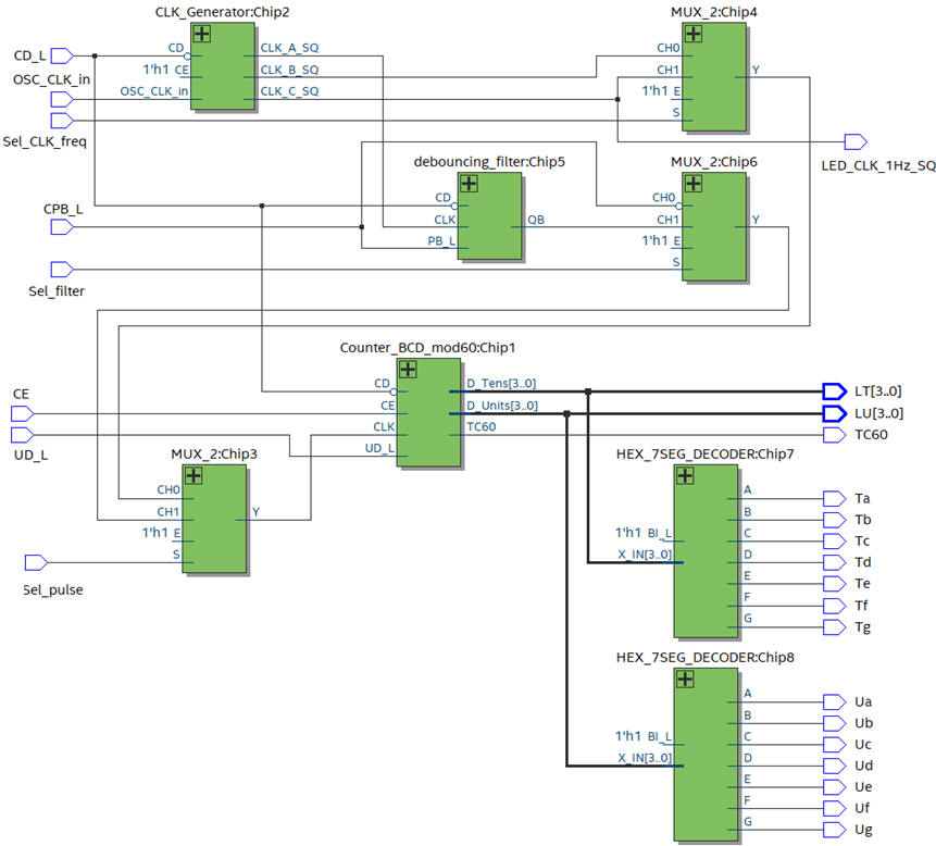 |
| Fig. 5. RTL view. |
Functional test in a VHDL testbench.
 |
| Fig. 6. VHDL testbench. |
2. ispLEVER Classic project
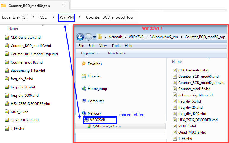
In this next stage, we can switch computers and tools to be able to target the obsolete ispMACH4128V device. Let us use the VM running Windows 7 and ispLEVER Classic tool for synthesis. Use the shared drive to copy the VHDL source files.
 |
|
Fig. 7. Shared folder strong> C:\CSD\VM_W7 between Windows 11 and the Window 7 VM. |
Let us start a new VHDL project for the ispMACH4128V CPLD including all the imported VHDL files. If we have to use the same environment for different legacy chips, it is convenient to organise the projects in separated folders. For instance:
C:\CSD\JK_HWD\Counter_BCD_mod60_top\(files)
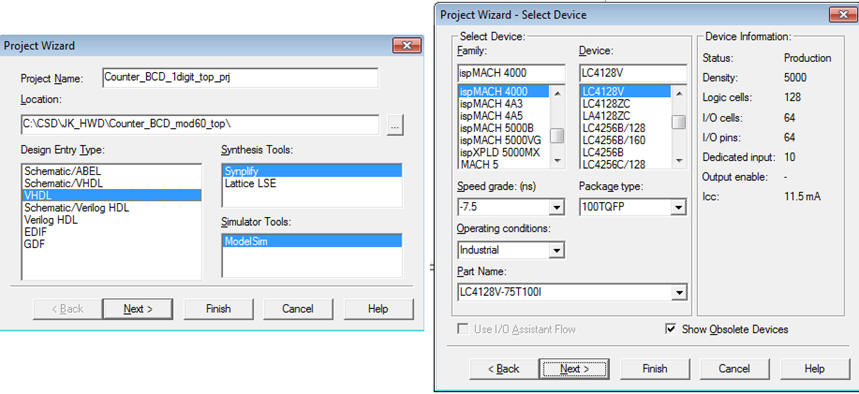 |
| Fig. 8. Starting an ispLEVER Classic project. |
Project synthesis.
 |
| Fig. 9. Project synthesis |
This is the full report generated by ispLEVER Classic: counter_bcd_mod60_top_prj.html. Once synthesised this project uses 38 registers D_FF.
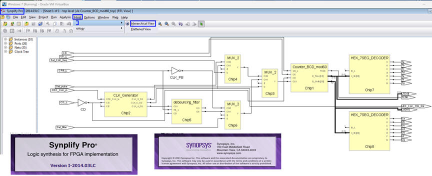 |
| Fig. 10. RTL view generated by Synplify Pro from Synopsys embedded in ispLEVER Classic. |
3. Pin assignment, configuration files
We use the Constraint Editor application to assign ispMACH4128V pins.
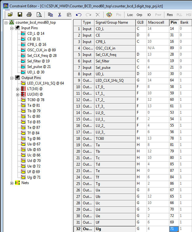 |
|
Fig. 11. Pin assignments spreadsheet as reported by the ispLEVER Classic Constraint Editor. |
The list of pin assignment can be imported from this file: counter_bcd_mod60_top_prj_pin.csv.
This is the top full project to be opened in ispLEVER Classic Counter_BCD_mod60_top.zip. And this is the final jed file to be programmed using the current Lattice Diamond in Windows 11.
4. Programming the CPLD using the *.jed and the ispVM System Lattice programmer
To download the configuration file Counter_BCD_mod60_top_prj.jed into the CPLD we use the latest Lattice Semiconductor Diamond Programmer.
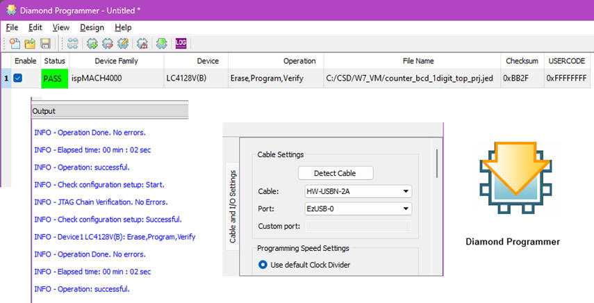 |
|
Fig. 12. Diamond Programmer. |
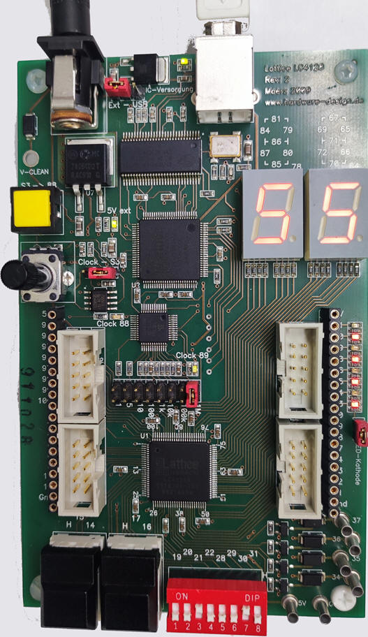
This is a picture of the prototype running.
 |
|
Fig. 13. Board running the counter application. |


