|
|
Bachelor's Degree in Telecommunications Systems and in Network Engineering |
|
L12.2: Timer/counter embedded peripherals. TMR0/TMR2 [P12] Peripherals: TMR0/TMR2 as a time-base for timing applications. |
[15 Dec] |
3.8. Peripherals: TMR0 timer/counter and TMR2 timer
3.8.1. TMR0 hardware circuit and configuration registers
Peripheral hardware and configuration bits and registers: CLK edge, CLK source, prescaler selection, TMR0 in 8-bit or 16 bit mode, hardware interrupt flag TMR0IF and software variable var_TMR0_flag at the ISR().
Design equation for timing periods TP using TMR0.
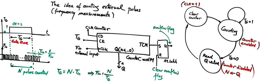
Using the TMR0 as a counter of external pulses
3.8.2. TMR2 hardware circuit and configuration registers
Design equation for timing periods TP using TMR2.
Explain why there is TP inaccuracy when using TMR0. How to solve it? What is the main advantage of replacing TMR0 by TMR2?
3.8.3. Examples
3.8.3.1. Serial transmitter with TMR0 (P12) {s_trans_LCD_TMR0} (design phase#3)
Timer using an internal peripheral TMR0 to generate the time-base var_CLK_flag. Let us discuss how the functionality assigned to the counter and the time base circuits in the datapath can be covered by the peripheral TMR0 embedded in the μC. TMR0 replaces the previous time-base (external CLK interrupt INT0).
Study the hardware-software diagram of the timer: Prescaler (N1), counter (N2), (software) postscaler (N3)
How to increase counting capacity? Software variables like var_Postscaler (N3).
3.8.3.2. Serial transmitter with TMR2 {s_trans_LCD_TMR2} (design phase#4)
3.8.3.3.Timer_LCD_TMR0 (design phase#3). Circuit developed and tested in Lab11.
Discussion on limitations of TMR0. References. More topics related to hardware timers: timer overhead, run-time overhead.
3.8.3.2.Timer_LCD_TMR2 (design phase#4)
Activity #1: Configure the PIC18F46K22 microcontroller with an 8 MHz oscillator crystal and utilise its TMR2 peripheral to generate timing periods of TP1 = 35.6 ms and TP2 = 35.6 s. Provide the design equations, a block diagram illustrating the hardware and software components, and specify the peripheral and interrupt configuration bits.
Activity #2: Use the PIC18F46K22 microcontroller operating with an 8 MHz oscillator crystal, utilising its TMR0 and TMR2 peripherals to count external events such as vehicles crossing a road sensor embedded in the tarmac. The system has a range of up to 10000 vehicles per hour. Explain how to include in the system measurements of the traffic flow in vehicles per minute.
| Home Term 26/27-Q1 Contact Products Electronic devices and companies Software Books Magazines Instruments DEE Library EETAC DEEL |

|
|
| Web activa des de 09/2001, @ F. J. Robert, Web editat amb Microsoft Expression Web 4. El contingut és un complement als materials d'estudi del curs Circuits i Sistemes Digitals disponibles al campus digital Atenea. Llicència:Reconeixement 4.0 Internacional de Creative Commons |