|
|
Bachelor's Degree in Telecommunications Systems and in Network Engineering |
|
|
Basic concepts on TMR0 |
||
A) How to use the embedded TMR0 as a timer?
B) How to use the embedded TMR0 as a counter of external events?
1. Architecture and configuration bits
Study peripheral timer TMR0 architecture and configuration possibilities rec. If TOCS = 1, it is a counter of external pulses (events); if TOCS = 0, is a timer derived from the internal time-base FOSC/4. The way TMR0 works is explained in datasheet chapter 11.
|
|
|
Fig 1. TMR0 embedded peripheral available in Microchip PIC family. The block diagram is a kind of RTL. A similar one can be found for any other peripheral timer like TMR1 or TMR2 of the same family. Similar timers-counters are also available in all other microcontrollers. |
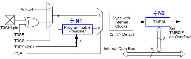
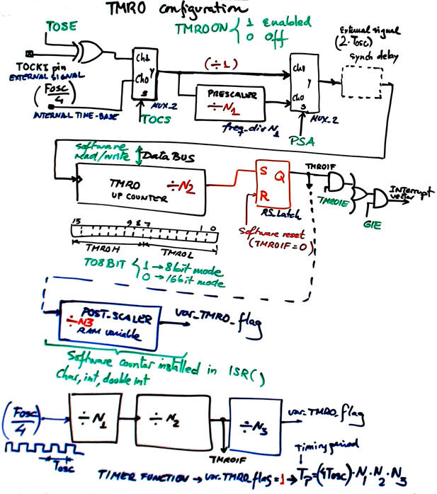
Fig.2 shows how the datasheet diagram can be interpreted considering interrupts (TMR0IF) and software post-scaler variables (N3) placed in the ISR() for generating any timing period TP when working as a timer and counting any arbitrary large number of pulses when working as a counter.
|
|
|
Fig 2. Circuit analysed from CSD point of view. |
2. Example project (TMR0 as timer): 18.5 s timer driven by an internal time base based on TMR0
- Timer_LCD_TMR0 (design phase #3 of the tutorial 18.5 s timer in Lab11)
3. Example project (TMR0 as counter): Counter of external events
We can very well use the TMR0 as a counter of events (falling or rising edges) at pin T0CKI (RA4).
 |
|
|
|
Fig 3. TMR0 block diagram indicating how to use it for counting external events. |
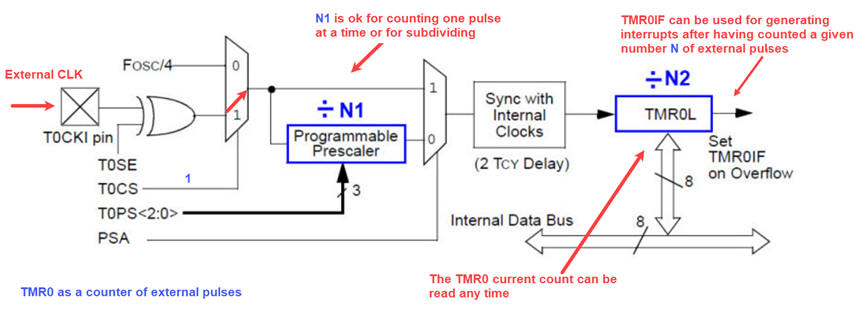
Thus, both options are possible for counting: (1) reading (polling) the current value of the counter TMR0 any time required by the software, or instead, (2) generating interrupts TMR0IF every certain number NP of pulses.
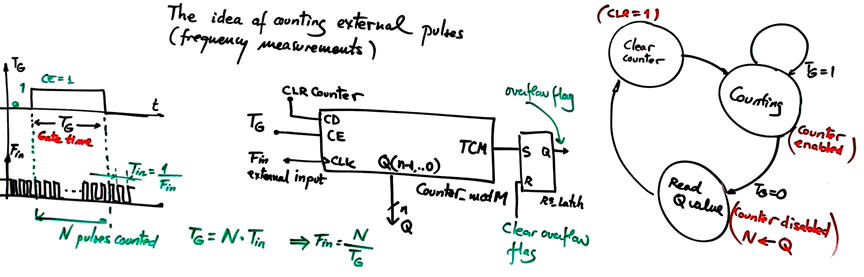
When applied for measuring frequency, TMR0IF can be used as an overflow error signal (the unknown frequency is that high that the counter's terminal count has been set and the counter has reinitialised generating when read an incorrect value).
For instance, we can continue the tutorial application Counter_BCD_1digit_LCD (design phase #2) adding a new design phase #3 as follows:
Counter_BCD_1digit_LCD_TMR0 (design phase #3): Liberate the INT0 so that it can be used for other future applications in the Counter_BCD_1digit_LCD replacing the INT0 (pin RB0) by the TMR0 working as a counter of external events.
Step #1: Implement the circuit so that the BCD count is updated every single external pulse
Step #2: Implement the circuit so that the BCD count is updates every three external pulses
|
|
|
Fig 4. New symbol for the design phase #3. |
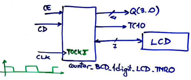
This is the tutorial Counter_BCD_1digit_LCD_TMR0 where this application is solved using TMR0 replacing the external INT0 pin (counting a single pulse and interrupting).
| Home Term 26/27-Q1 Contact Products Electronic devices and companies Software Books Magazines Instruments DEE Library EETAC DEEL |

|
|
| Web activa des de 09/2001, @ F. J. Robert, Web editat amb Microsoft Expression Web 4. El contingut és un complement als materials d'estudi del curs Circuits i Sistemes Digitals disponibles al campus digital Atenea. Llicència:Reconeixement 4.0 Internacional de Creative Commons |