|
|
Bachelor's Degree in Telecommunications Systems and in Network Engineering |
|
L12.1: Adapting dedicated processor applications [P12] Project 18.5 s fixed-time timer. FSM + datapath() |
[11 Dec] |
3.7. Dedicated processors in C (datapath, control unit)
3.7.1. Hardware-software diagram
3.7.2. Examples
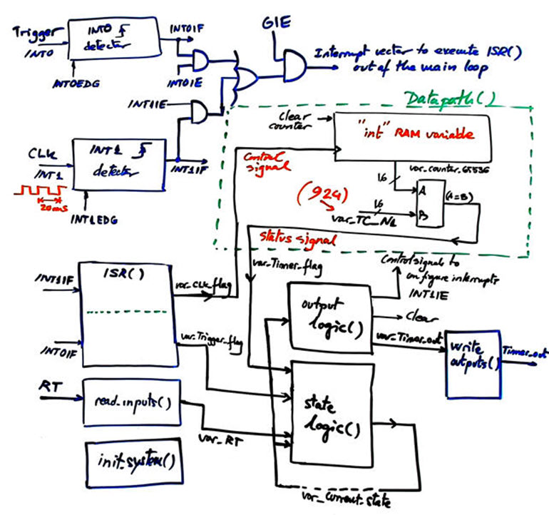
3.7.2.1. Timer circuits. Let us propose a simple circuit in several design phases (design phase #1)
Circuit developed and tested in Lab11.
What are the specifications of a Timer? What is the meaning or triggering and re-triggering?
Review the highlighted Timer_MMSS project implemented for an FPGA in Chapter II as a dedicated processors (P8).
Infer how our fixed-time timer can be conceived. Why the datapath do not have to be operating continuously?
What is the difference if the timer timing period is in the range of ns, ms, minutes or weeks?
Discuss the adaptation to the PIC18F4520:
- Hardware. External CLK time base (INT1) and trigger button (INT0).
- Software. FSM controlled by the trigger button (INT0). Datapath (counter RAM variable) enabled only when required.
3.7.2.2. Timer_LCD (design phase#2)
Enhance the fixed-time Timer of 18.5 s with an LCD, so that ASCII messages can be represented to indicate how the system operates.
Circuit developed and tested in Lab11.
|
|
3.7.3. Examples: event counter
3.7.3.1. Tachometer, speed meter, odometer
Activity #1: Discuss how the hardware-software diagram below may be an adaptation of the dedicated processor required for timing TP = 18.5 s.
| Home Term 26/27-Q1 Contact Products Electronic devices and companies Software Books Magazines Instruments DEE Library EETAC DEEL |

|
|
| Web activa des de 09/2001, @ F. J. Robert, Web editat amb Microsoft Expression Web 4. El contingut és un complement als materials d'estudi del curs Circuits i Sistemes Digitals disponibles al campus digital Atenea. Llicència:Reconeixement 4.0 Internacional de Creative Commons |