|
|
Bachelor's Degree in Telecommunications Systems and in Network Engineering |
|
|
Basic concepts on TMR2 peripheral |
||
A timer with hardware parallel load
1. Architecture and configuration bits
Study peripheral timer TMR2 architecture and configuration possibilities.
- Search for the peripheral section in the microcontroller datasheet.
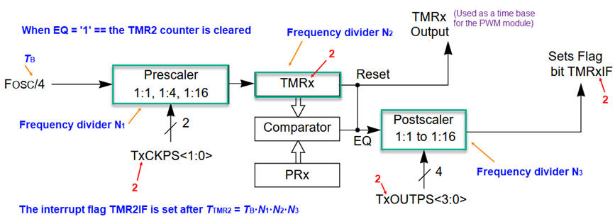
- Analyse the peripheral's schematic or block diagram in Fig. 1. Determine what is its main characteristic compared with TMR0.
- Determine its design equation on how to use it in our applications.
|
|
|
Fig 1. Hardware components (a kind of RTL view) of the TMR2 of the Microchip PIC18F46K22. |
|
|
|
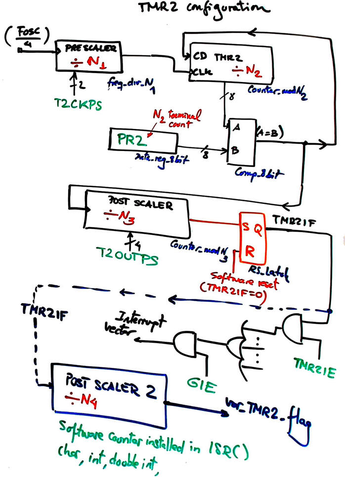
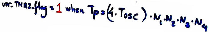
Fig 2. Interpretation of TMR2 architecture using CSD conventions. Thus, a var_TMR2_flag is generated after a timing period TP. |
2. Example project: 18.5 s timer driven by the internal TMR2 time-base
- Timer_LCD_TMR2 (design phase #4 of the tutorial 18.5 s in P12)
| Home Term 26/27-Q1 Contact Products Electronic devices and companies Software Books Magazines Instruments DEE Library EETAC DEEL |

|
|
| Web activa des de 09/2001, @ F. J. Robert, Web editat amb Microsoft Expression Web 4. El contingut és un complement als materials d'estudi del curs Circuits i Sistemes Digitals disponibles al campus digital Atenea. Llicència:Reconeixement 4.0 Internacional de Creative Commons |