|
|
Bachelor's Degree in Telecommunications Systems and in Network Engineering |
|
|
Simple timer circuits |
||
R-C, 555, and other timers
1. Timer circuits
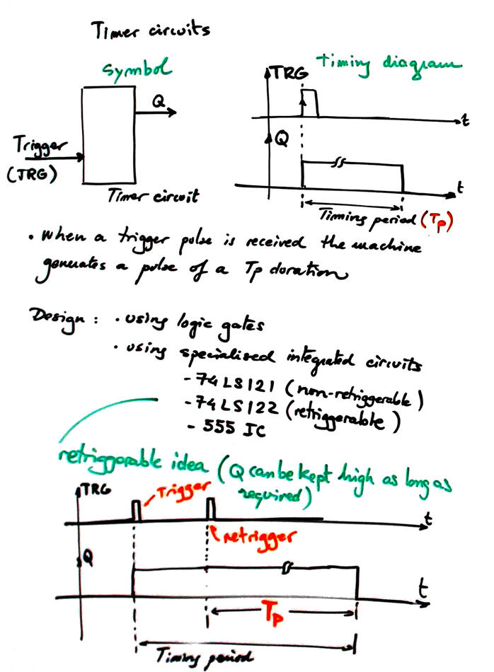
The idea of a timer circuit is represented in Fig. 1. Slide.
 |
|
Fig. 1. Symbol and operation of timer circuit. There is also for some circuits the extra retriggerable feature that allows enlarging timing period as much as desired. |
|
|
2. Timer circuit based on logic gates
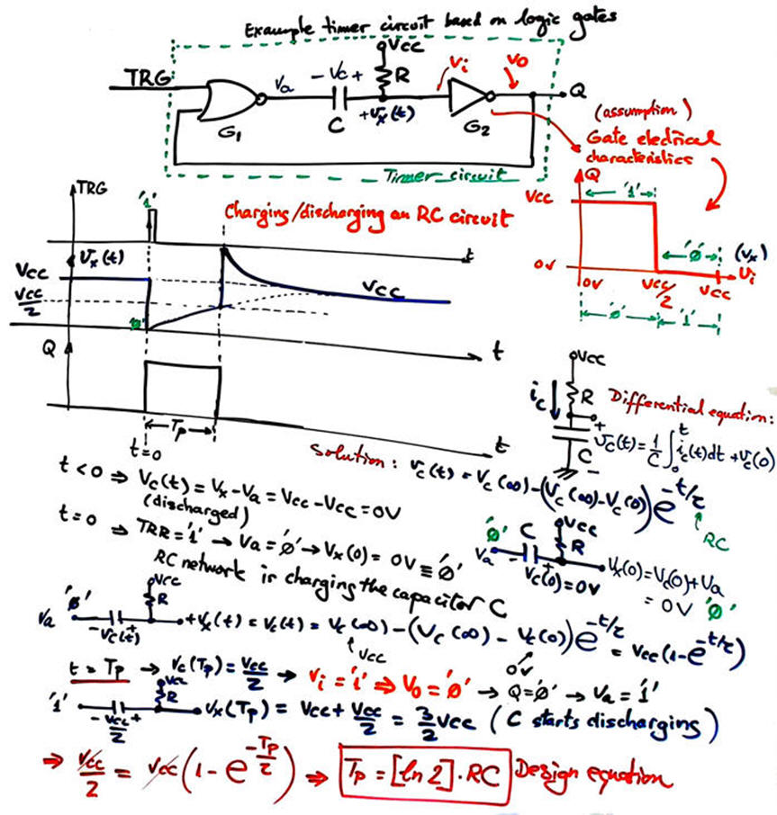
Fig. 2 shows the typical RC timer based on logic gates and on the idea of charging and discharging a capacitor. The analysis in Fig. 3 shows how to deduce its timing period (TP).
 |
Fig. 2. Typical RC timer. Time constant determines the circuit timing period along with technology values associated to low (NML) and high (NMH) logic margins. |
Analysis of this basic circuit is presented in Fig. 3.
 |
|
Fig. 3. Analysis of a typical circuit based on logic gates. Let us assume that the transfer I/O characteristics of the logic gates are simplified as shown: no forbidden zone, but half of the input voltage margin interpreted as VIL, and the other half as VIH. |
Typical classic timer integrated circuits are 74LS122 (retriggerable) and 74LS121 /74HCT221 (non retriggerable).
|
|
3. Timer circuit based on 555 chip
Fig. 4 shows the typical timer based on the 555 classic circuit . This analysis shows how to deduce its timing period. This is the circuit 555_timer in Proteus.
 |
Fig. 4. Typical timer based on 555 classic circuit. |
Example application: Circuit simulator of the ultrasonic sensor HC-SR04: 555_distance_sensor.pdsprj
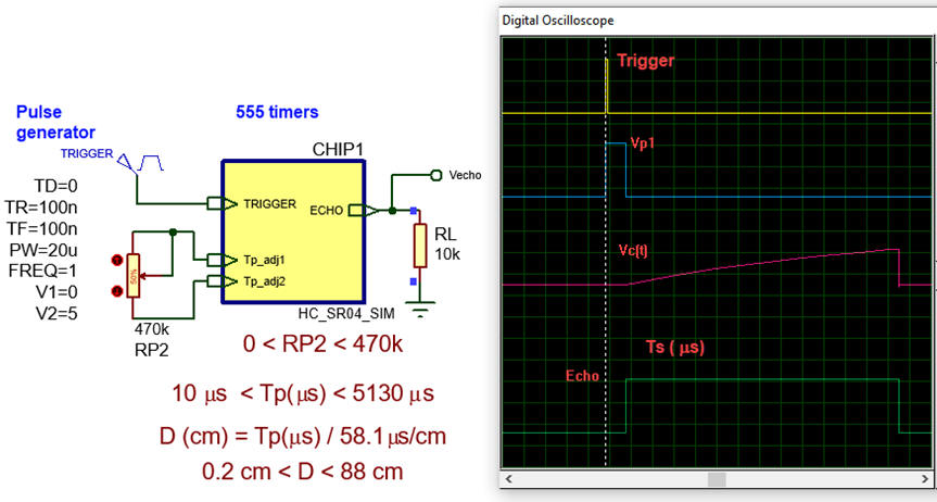 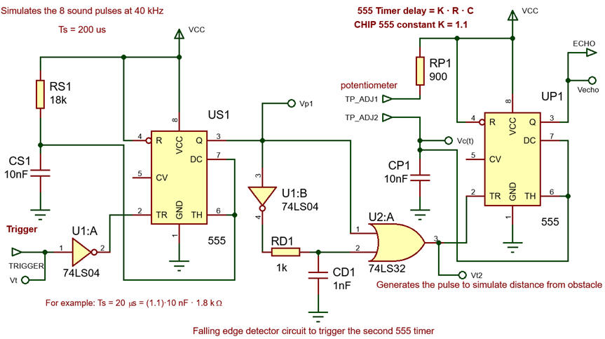 |
|
Fig. 4. HC-SR04 ultrasonic Sensor Module simulator. |
| Home Term 26/27-Q1 Contact Products Electronic devices and companies Software Books Magazines Instruments DEE Library EETAC DEEL |

|
|
| Web activa des de 09/2001, @ F. J. Robert, Web editat amb Microsoft Expression Web 4. El contingut és un complement als materials d'estudi del curs Circuits i Sistemes Digitals disponibles al campus digital Atenea. Llicència:Reconeixement 4.0 Internacional de Creative Commons |