|
|
Bachelor's Degree in Telecommunications Systems and in Network Engineering |
|
|
16-key matrix encoder |
FSM, external interrupts INT0, state enumeration
| 1. Specifications | Planning | Dev. & test | Prototype | report |
Implement the P6 16-key matrix encoder using a PIC18F46K22 microcontroller chip. Software is organised as usual mimicking a FSM synchronised by interrupts from an external oscillator CLK.
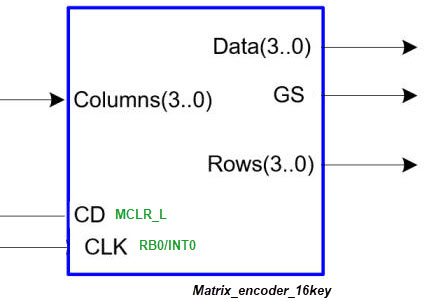 |
Fig 1. Symbol of the Matrix_encoder_16key to be designed using a FSM architecture. This circuit can be compared to the combinational equivalent Enc_16_4 studied in P2 or the FSM version in P6. |
Features:
- Data output shows the HEX value of the key pressed.
- GS pulse is active while clicking.
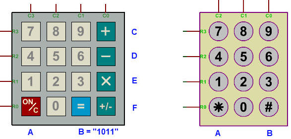 |
Fig. 2. Example Proteus modelled keypads from Matrix_keyboard.pdsprj. Keys with plastic labels that are not numbers such "*" are given other free hexadecimal codes as "1010" = A. |
| Specifications | 2. Planning | Dev. & test | Prototype | report |
A) Planning hardware
The proposed circuit is represented in Fig. 3. Some pins must be selected to be inputs and outputs, and in this case, external interrupt IINT0 is used to detect active CLK edges used for scanning the keypad rows.
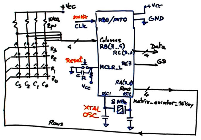 |
Fig. 3. Proposed hardware connections to mC pins. |
B) Planning software
We will organise the software as in P10. The idea of implementing a "FSM in software" with some functions related to hardware (drivers) and the internal output and state logic software functions that process RAM variables.
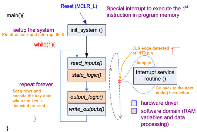 |
Fig. 4. Software organisation. It is interesting to remark that for this tutorial on a hardware driver (the matrix keypad device), the FSM (coloured brown) runs as the top main() function. When this project is used as a component for other projects, the FSM can be embedded as a function such get_key() to return the hexadecimal code of the key pressed. |
Represent the RAM variables required in this application as shown in Fig. 5.
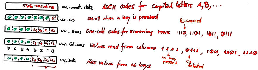 |
Fig. 5 RAM variables. |
This hardware-software diagram in Fig. 6 is fundamental to show and explain the main blocks conforming this FSM application. Orange functions work using RAM variables and standard C libraries, they are not constrained by hardware details of the specific target chip.
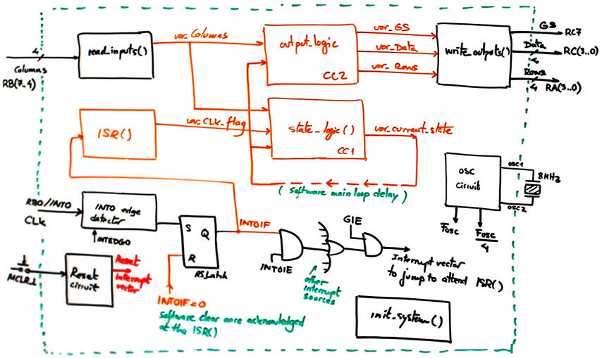 |
Fig. 6. Hardware-software diagram. |
Draw the FSM state diagram. As indicated, all the arrows are sensitive to CLK interrupts. Thus, the user can disable interrupts INT0 if required, to block inhibit the keypad circuit.
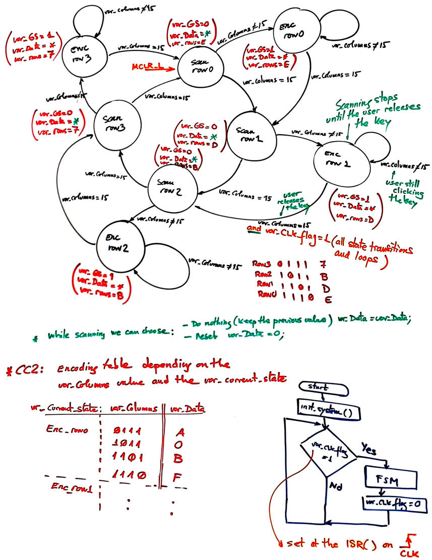 |
Fig. 7. Proposed state diagram. |
Draw the main ideas of init_system(). Configure input and output pins. Consider as well interrupts configuration.
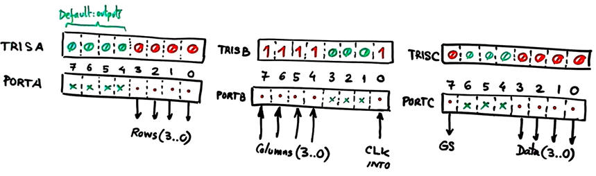 |
Fig. 8. Example of port direction configuration. ANSELx = 0x00 to make all pins digital I/O. |
Draw the flowchart, memory map and C code of read_inputs(). Basic function to poll input voltages as in L9.3.
Draw the flowchart, memory map and C code o write_outputs(). Basic function to write pin voltages as in L9.4.
Infer how to organise the interrupt service routine ISR() to handle CLK edge detections.
Draw state_logic() truth table and its behavioural interpretation as a flowchart.
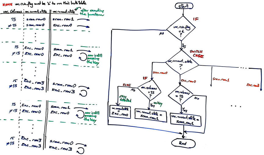 |
Fig. 9. State logic function (CC1) and its flowchart ready for C translation. |
Draw output_logic() truth table and its behavioural interpretation as a flowchart.
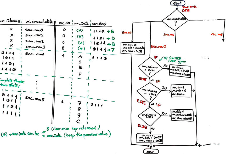 |
Fig. 10. Output logic function (CC2) and its flowchart ready for C translation. |
Organise a MPLABX - XC8 IDE project targeting a PIC18F46K22 at location:
C:/CSD/P10/Matrix_encoder_16key/(files)
| Specifications | Planning | 3. Dev. & 4. test | Prototype | report |
A) Developing hardware
Draw the schematic of the application in Proteus "Matrix_encoder_16key.pdsprj" copying and adapting an example or tutorial.
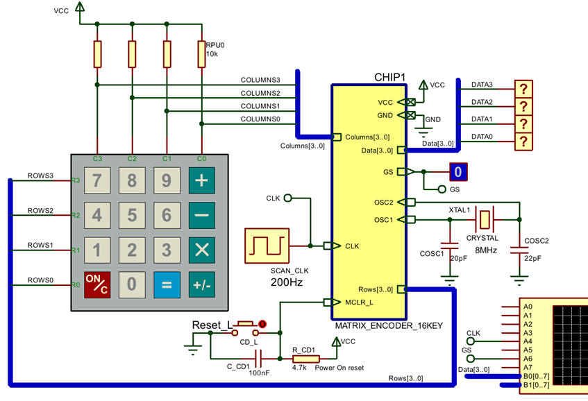 |
Fig. 11. The encoder captured in Proteus. |
B) Developing software
The C source file "Matrix_encoder_16key.c" for step #1 where only count enable and up counting are developed. Add the "config.h" header to your project to fix the mC configuration bits.
C) Step-by-step testing
Run the Proteus simulator. Do it in step by step mode while watching variables and placing break points, specially for following interrupt flags.
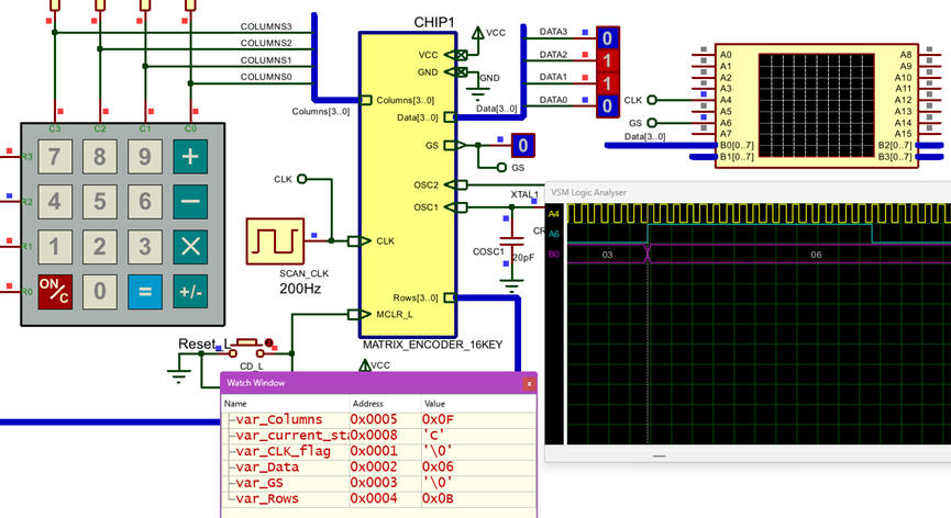 |
Fig. 12. The circuit in "run" mode while monitoring the variables in the "watch" window. |
| Specifications | Planning | Dev. & Test | 5. Prototype | Report |
You're invited to download the application to the CSD_PICstick training board an verify that it works as expected. You can add instruments such the logic analyser from the VB8012 to capture and visualise the circuit waveforms.
| Specifications | Planning | Dev. & Test | Prototype | 6. Report |
Project report: sheets of paper, scanned figures, file listings, notes or any other resources. Follow this rubric for writing reports.
| Home Term 26/27-Q1 Contact Products Electronic devices and companies Software Books Magazines Instruments DEE Library EETAC DEEL |

|
|
| Web activa des de 09/2001, @ F. J. Robert, Web editat amb Microsoft Expression Web 4. El contingut és un complement als materials d'estudi del curs Circuits i Sistemes Digitals disponibles al campus digital Atenea. Llicència:Reconeixement 4.0 Internacional de Creative Commons |