|
|
Bachelor's Degree in Telecommunications Systems and in Network Engineering |
|
|
Basic concepts on external interrupts |
||
How to detect active signal edges and enhance program execution?
1. Polling vs. interrupts
The key concepts of polling inputs in the main program and interrupts to the main program. Polling is cyclical and repetitive because is installed in the main loop, however, it is not a periodic process because the specific timing in which signals are polled depends on the loop execution time, software bifurcations and number of instructions in each path before repeating the loop. Activating an interrupt to the main program is a totally different concept that allows the detection of active edges with precision.
2. External interrupt circuit. Port pin and edge detection concept (hardware flag)
A port pin with INT specialised hardware rec..
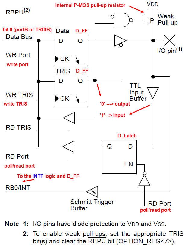 |
Fig. 1. Electronic circuit for PORTB as presented by
Microchip. As a generic PORTx is
studied in detail in this
unit on
input/output configuration. This time, we pay attention to the bottom section of the schematic related to the specificity of RB0/INT; the pin is an edge sensitive input connected to INTF edge detector to allow external interrupts. |
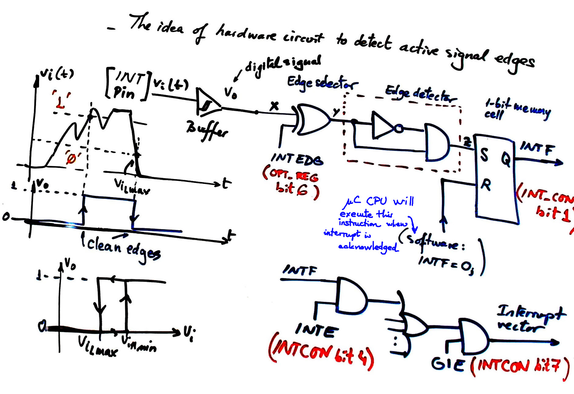
These are a couple of slides (1) (2) on how an interrupt circuit may be designed. The concept to detect an active edge (edge detector) may be similar to converting the external CLK signal into enable (E) when studying how to design an RS_FF from an RS latch in P5.
The idea of the Schmitt-trigger comparator/buffer with hysteresis transfer function.
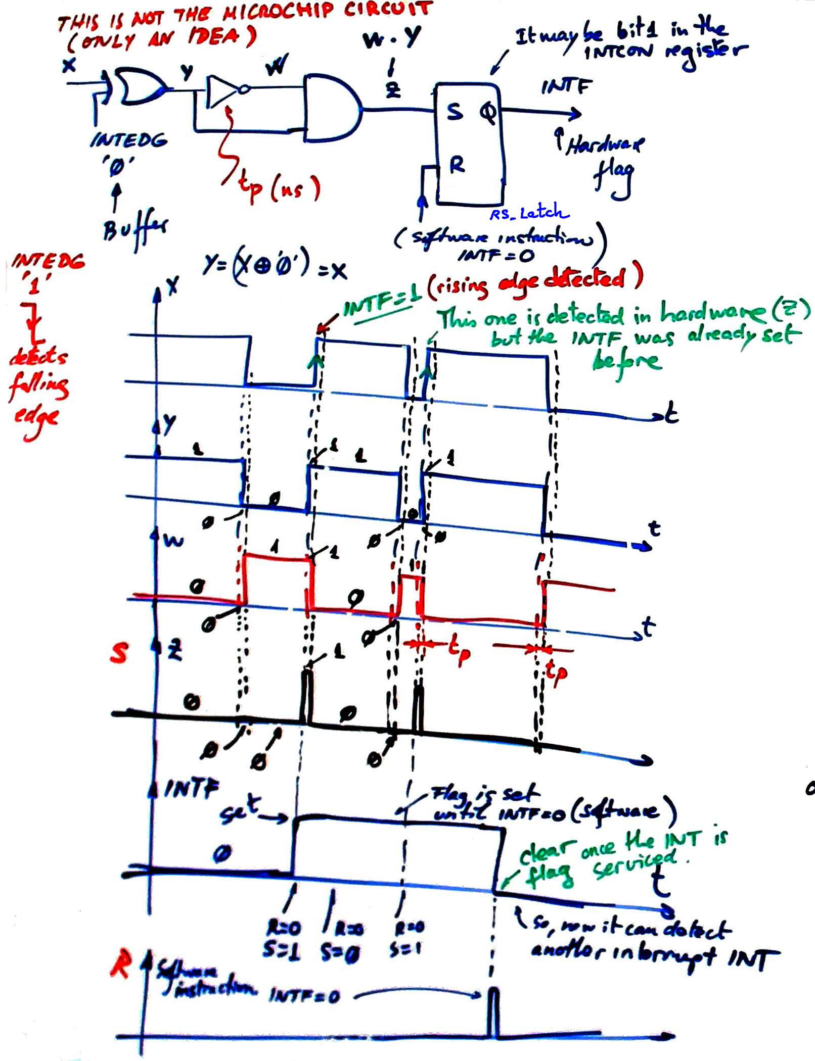
3. Example of falling or rising edge detector
This is an example of falling/rising edge detector based on logic gates.
 |
|
Fig. 3. When EDG = 0, the NXOR gate becomes a NOT gate and the circuit generates tiny pulses on falling edges considering tP propagation delay on the NOT gate C = B'. Example of edge detector in Proteus: the 4049 CMOS inverter has a larger propagation delay than LS-TTL gates, enough time to set the latch. |
And the idea on how an external active edge detected at port B pin 0 can generate interrupt INT0 is represented in Fig. 4. This port B has as well the possibility to use internal transistors P-MOS acting as pull-up resistors when configured by bit RBPU_L (port B pull-up), in this way we can save external resistors attached to push-buttons and switches.
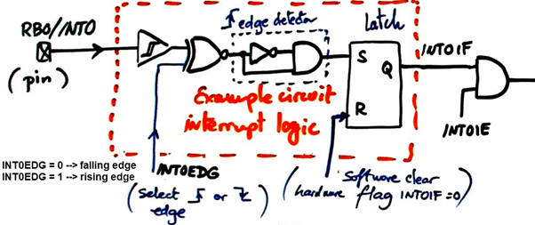 |
|
Fig. 4. Example of interrupt hardware. |
4. Interrupt logic to enable and attend interrupts
Fig. 5 shows the PIC18F46K22 datasheet schematic for the interrupt logic. User can enable or disable any interrupt source and also define interrupt priority. Configuration bits allows controlling which device is allowed to interrupt the CPU main program.
 |
|
Fig. 5. Representation of the PIC18F46K22 interrupt logic. |
Other common sources of interrupt are TMR0IF and TMR2IF. Interrupts on change in RB pins will be described in unit RB_INT.
5. Interrupt service routine. Software flag
Finally, what we do in CSD once the interrupt is acknowledged is to set a software flag such var_ST_flag, simply another RAM char variable, to be able to assert state diagram transitions. Study several examples in P10, P11 and P12 to analyse this mechanism.
Remark the difference of the interrupt mechanism with respect to the polling/reading mechanism that only happens when the main loop is executing instructions in read_inputs(), generating a variable polling time of the input level at the speed of loop execution missing signal transitions.
 |
|
Fig. 6. This slide explains polling and interrupt mechanisms. |
| Home Term 26/27-Q1 Contact Products Electronic devices and companies Software Books Magazines Instruments DEE Library EETAC DEEL |

|
|
| Web activa des de 09/2001, @ F. J. Robert, Web editat amb Microsoft Expression Web 4. El contingut és un complement als materials d'estudi del curs Circuits i Sistemes Digitals disponibles al campus digital Atenea. Llicència:Reconeixement 4.0 Internacional de Creative Commons |