|
|
Bachelor's Degree in Telecommunications Systems and in Network Engineering |
|
L9.3: basic I/O. Poll/read input values [P9] read_inputs() |
[24 Nov] |
3.4.2.2.3. read_inputs()
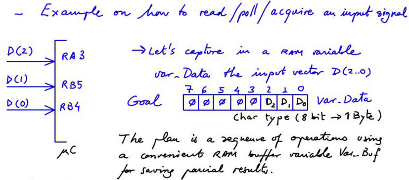
Our goal: How to poll/capture/read input port pins? How to convert electrical signals (digital voltages) into RAM variables?
 |
|
Fig. 1. Example on how to read inputs. |
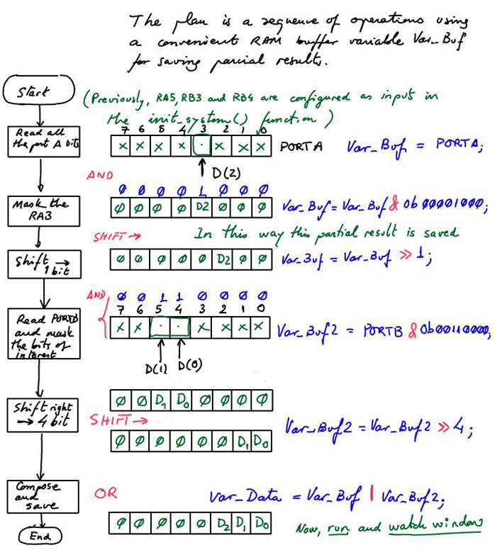
Our plan: Mask, clean, shift and organise bits in convenient RAM variables using bitwise logic operations (AND, OR, XOR, NOT, SHIFT) implemented by the μC ALU. Fig. 2 is an example planning sheet on how to read (or poll/acquire/capture) a signal connected to a μC pin and convert it into a convenient RAM variable. In this way it is easy to deduce which C instructions are required in the source file.
The similar idea of sampling an input at a given CLK active edge is a more complex concept to be explained in P10 on the use of external interrupts to the main program.
 |
|
Fig. 2. Sequence of bitwise operations using a flowchart with rectangle symbols, (pdf), memory position diagrams representing how the bits of interest are processed and its ranslation to C code. |
Study how read_inputs() is organised in Adder_BCD_1digit.
3.4.3. Development & testing
Our target μC device: chip PIC18F46K22 from Microchip.
3.4.3.1. Hardware schematic capture: pdsprj file.
The simulation and testing tool to install in your computer using our cloud license: Virtual laboratory Proteus VSM.
3.4.3.2. Software development in C language
The IDE (integrated software development environment) to install in your computer: MPLABX with its C compiler XC8.
3.4.3.3. Project compilation and chip configuration files: hex, cof
Compiler options: C99, COFF output file generation.
3.4.3.4. Proteus simulation and testing. Step by step debugging, watch variables window
Run/stop, watch window, RAM variables, ROM (program memory), MCU registers and flags, step by step mode, break points, etc.
Typical measurements:
- Main loop execution time. How fast is our circuit solving a truth table?
- Disassembly mode. How long does it take to execute an instruction in assembly?
- Execution time of a section of code. How long does it take to execute an instruction in C?
. Run the same measurements using different crystal µC oscillators (4 MHz, 12 MHz, etc.). Adjust this parameter for the PIC18F46K22 in edit properties.
Activity #1: Input pin connections: Data(3..2) ---> RC(4..5), be aware of the pins flipped order; Data(1..0) ---> RB(7..6). Explain in the three-columns report sheet the flowcharts, content in RAM memory variables, bitwise operations and C code translation for reading the variable var_Data.
Activity #2: Read an input pin from the assigned PLA9 circuit. In the three-column report sheet provided in this unit (Fig. 2), describe the flowcharts, the contents of RAM memory variables, the bitwise operations, and the C code translation used to capture the input pin and transfer its binary information into a RAM variable.
If you work in teams, each group member reads a different input.
| Home Term 26/27-Q1 Contact Products Electronic devices and companies Software Books Magazines Instruments DEE Library EETAC DEEL |

|
|
| Web activa des de 09/2001, @ F. J. Robert, Web editat amb Microsoft Expression Web 4. El contingut és un complement als materials d'estudi del curs Circuits i Sistemes Digitals disponibles al campus digital Atenea. Llicència:Reconeixement 4.0 Internacional de Creative Commons |