|
|
Bachelor's Degree in Telecommunications Systems and in Network Engineering |
|
|
Basic concepts on TMR1 peripheral (PIC18F46K22) |
||
TMR1 - TMR3 - TMR5 have similar architecture
1. Architecture and configuration bits
Study peripheral timer TMR1 architecture and configuration possibilities.
- Search for the peripheral section TMR1 in the microcontroller datasheet.
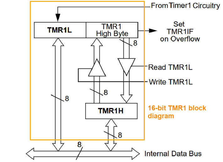
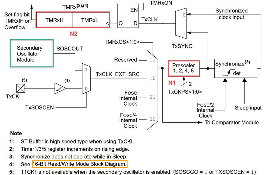
- Analyse the peripheral's schematic or block diagram in Fig. 1. Determine what is its main characteristic compared with TMR0.
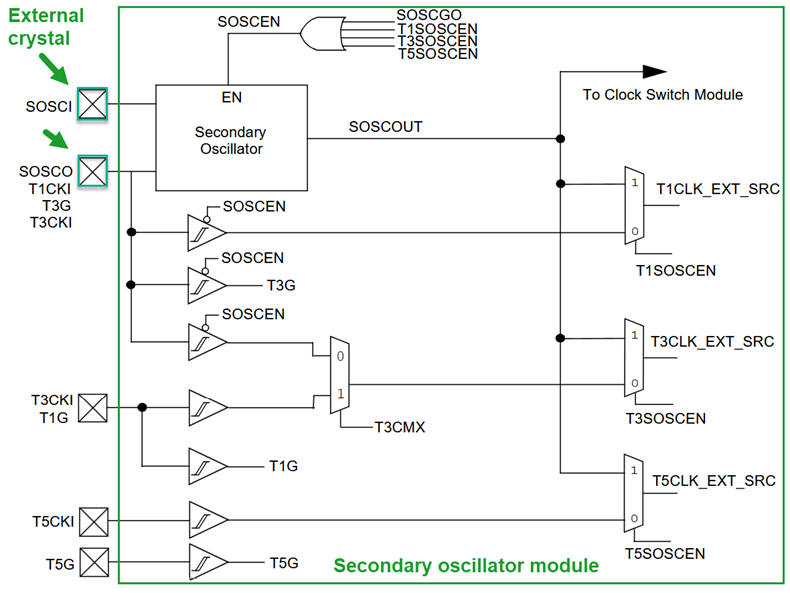
- Determine its design equation on how to use TMR1 as a counter of external events or timer using reference oscillators. We can choose between primary and secondary oscillators.
a)
b)
c) |
|
Fig 1. Simplified hardware components (a kind of RTL view) of the TMR1 of the Microchip PIC18F46K22 from its datasheet. a) TMR1 16-bit counter. b) Architecture, c) Secondary oscillator circuit. |
2. Example project
CSD_PICstick design phase #3 shows how to use TMR1 as a counter of external oscillator pulses for timing: a) 1 Hz and b) 12 Hz interrupts. In this application var_CLK_flag is the same as var_TMR1_flag.
|
|
|
Fig 2. Interpretation of TMR1 architecture using CSD conventions. Thus, a var_TMR1_flag is generated in the ISR() when the hardware TMR1IF interrupt is set after a timing period TP = TSOSC · N1 · N2 |
T1SOSCEN = 1
SOSCGO = 1
| Home Term 26/27-Q1 Contact Products Electronic devices and companies Software Books Magazines Instruments DEE Library EETAC DEEL |

|
|
| Web activa des de 09/2001, @ F. J. Robert, Web editat amb Microsoft Expression Web 4. El contingut és un complement als materials d'estudi del curs Circuits i Sistemes Digitals disponibles al campus digital Atenea. Llicència:Reconeixement 4.0 Internacional de Creative Commons |