|
|
Bachelor's Degree in Telecommunications Systems and in Network Engineering |
|
|
Microchip MPLAB Code Configurator MCC Melody |
Introductory tutorials (1) (2) (3) (4) (5) (6) (7) (8)
Hardware: CSD_PICstick. PIC18F46K22 or PIC18F26K22, MPLAB® Snap In-Circuit Debugger/Programmer or the newer MPLAB PICkit Basic In-Circuit Debugger.
Software: MPLABX IDE v6.25 or higher, XC8 compiler 3.00 or higher, C standard C99, MCC Melody.
Microchip reference documentation on MCC Melody. References on design patterns for control flow.
Project #1: Toggle LED using a push-button connected at INT0
This is the location of this full project Toggle_LED.
Project #2: Blink a LED at 4 Hz using TMR0 and a push-button connected at INT0 to count external edge events
Now, in this second tutorial, we will blink the LED using a TMR0 as the source of interrupts to set the intermittency timing period TP = 250 ms. The external INT0 connected to the PB_L will be used to increment a variable that will count the number of external interrupts acknowledged.
To learn "how to copy and adapt a MPLABX project", follow the indications and detailed steps supplied by the Google AI overview. Copy the content of the previous folder T1_Toogle_LED to a new T2_Blink_LED folder.
The project organisation is very similar to the first tutorial above. This is the zipped file: Blink_LED.zip.
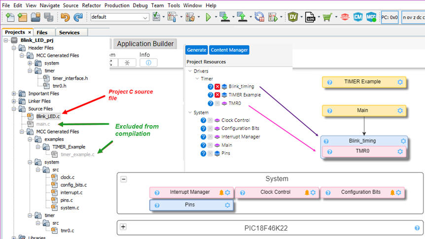
We will add our C code to the top "Blink_LED.c" file. The "main.c" template and other examples files generated by MCC may be excluded from compilation. But you can keep them in the project to experiment and study how the peripherals and the modules work.
We can study and fetch the basic examples from the Microchip reference. We use a generic Timer example and we relate it to TMR0 peripheral. We rename it as the Blink_timing resource.
|
|
|
Fig 1. Components from which to generate the MCC files. |
Compile and check how it works in Proteus or the CSD_PICstick board. Experiment with variations, such generating a 100 Hz square waveform to be visualised in the oscilloscope. Or use the external interrupt INT0 as the ON-OFF button.
Try to attach the Blink_timing resource to the TMR5 to observe how MCC is taking care of the hardware layer of your application saving for you the developing time associated to the bare-metal programming.
Project #3: FSM control flow. Blinking LED using TMR0 and a push-button connected at INT0 to switch ON/OFF
The final idea left for this third tutorial is to control the program flow using a FSM pattern, as we do in CSD. Reference from Microchip University on this idea.
-
Blink_timing resource from TMR0.
-
External push-button ST_L connected to INT0 for turning the application ON-OFF.
-
A switch P to choose 5 Hz or 200 Hz.
This is the location of the full project Blink_LED_FSM.
Project #4: PWM peripheral driver.
Let us try the PWM peripheral made available directly from MCC. Generate a 1 kHz rectangular (DC = 30%) waveform
Project #5: Push-button debouncing filter
Let us try to eliminate ON/OFF button bounces and digital noise for a push-button or key connected to a microcontroller.
This is the location of the full project Debouncing_filter.
The same tutorial can be used to learn on projects running several FSM.
Project #6: 1-digit BCD counter
This project includes an start/stop push-button driven by external interrupt INT0. This is the page of the full project Counter_BCD_1digit; the MCC version of the CSD LAB10 tutorial.
Project #7: 1-digit BCD counter with LCD using I2C libraries
This project includes an start/stop push-button driven by external interrupt INT0. This is the page of the full project Counter_BCD_1digit_LCD, the MCC version of the CSD LAB11 tutorial. Annex A3 contain the I2C-LCD library.
Project #8: FSM with A/D converter and LED bar
This project includes an start/stop push-button driven by external interrupt. This is the page of the full project FSM_AD_LEDbar.
Other MCC introductory example projects can be found at the Dimmer capstone project.
| Home Term 26/27-Q1 Contact Products Electronic devices and companies Software Books Magazines Instruments DEE Library EETAC DEEL |

|
|
| Web activa des de 09/2001, @ F. J. Robert, Web editat amb Microsoft Expression Web 4. El contingut és un complement als materials d'estudi del curs Circuits i Sistemes Digitals disponibles al campus digital Atenea. Llicència:Reconeixement 4.0 Internacional de Creative Commons |