|
|
Bachelor's Degree in Telecommunications Systems and in Network Engineering |
|
|
|
1-digit BCD counter with LCD (I2C interface) and MCC Melody |
| 1. Specifications | Planning | Dev. & test | Prototype | Report |
- Inherit and adapt the previous Counter_BCD_1digit.
- Add the standard typical I2C - LCD interface as shown in Fig. 1. The typical hardware based on the I2C chip expander PCF8574 (TI and NXP datasheets) and the LM016L LCD (presented in CSD P11).
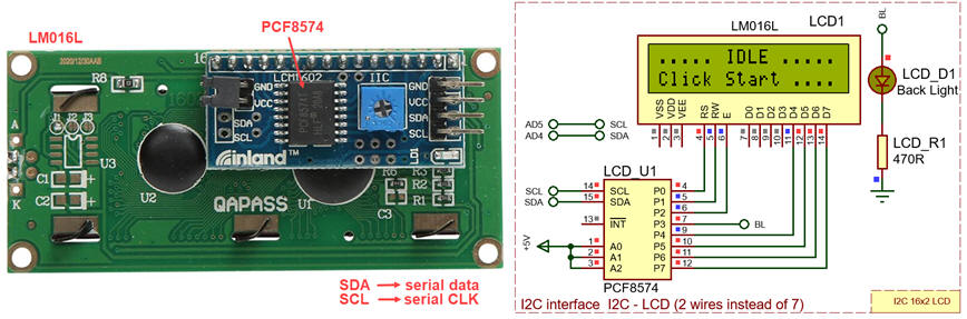  |
Fig 1. Standard LCD driven by a bus expander chip compatible with the synchronous I2C serial I2C interface. |
Some references to imagine how it may be inferred: ref1., ref2., ref3. In addition to fixing the new hardware, to proceed with this idea, we need to find or develop a C language high-level LCD library for the XC8 compatible with the MCC Melody I2C libraries.
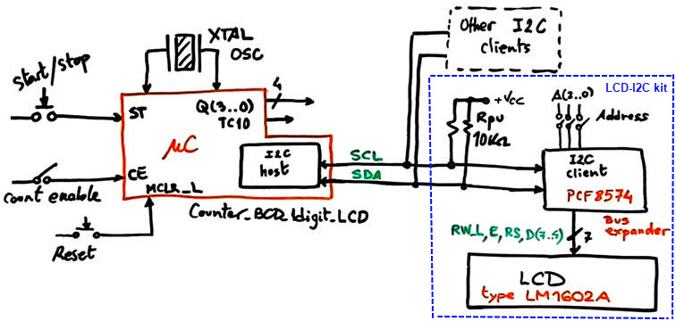 |
Fig. 1. Application symbol emphasising the new I2C bus connection where to attach client devices. |
| Specifications | 2. Planning | Dev. & test | Prototype | Report |
The basic LM1602A LCD with a parallel 6-wire interface is introduced in CSD LAB11. We will plan several incremental design steps to discover how to add an LCD with I2C interface to the CSD_PICstick and be able to program the application using the MCC Melody. The three initial projects are presented as annexes and the fourth step becomes the main project in this tutorial.
This planning sequence assumes enhancement to the inherited Counter_BCD_1digit.
The two initial steps may be used as an introduction to the I2C bus:
Annex A1: I2C step #1: Discover the I2C, find and study a Microchip application note on using the I2C through MCC Melody. Enable the microcontroller's master synchronous serial port (MSSP) peripheral for serial communication.
Annex A2: I2C step #2: Add I2C bus expander PCF8574 client and run it using the I2C library.
Another step will be required for sending commands and data to the LCD by means of the bus expander.
Annex A3 LCD step #1: Add the LCD controlled by the bus expander and develop the LCD library of functions.
Finally, after the three initial tutorials, we will apply the LCD library to solve this project.
LCD step #2: implement the Counter_BCD_1digit_LCD through the serial interface I2C.
A) Planning hardware
The same hardware from the LCD step #1 simplified as shown in Fig. 1, leaving only the LCD - I2C kit at the default address 0x27.
B) Planning software
Use the MCC Melody to print the BCD counter values on the LCD screen.
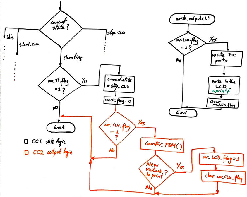 |
Fig. 4. To test the program and how it is printing ASCII characters on the LCD, we will print the BCD counter numbers. We will be able to use the standard sprintf function. Writing will happen only at the CLK edge (on TMR0IF overflow) and only when new information is generated (var_LCD_flag = 1). |
Project location:
C:\DEE\LAB7\PIC18F\Counter_BCD_1digit_LCD\(files)
| Specifications | Planning | 3. Dev. & 4. test | Prototype | Report |
Let us compile the main "Counter_BCD_1digit_LCD.c" along with LCD and I2C header and source files.
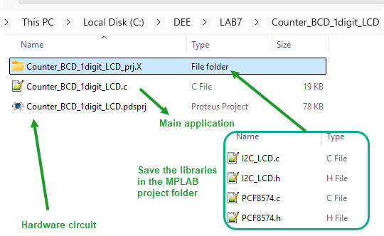 |
Fig. 5. The project will include up to five source files. |
The full project "Counter_BCD_1digit_LCD.zip" and the LCD and I2C libraries from the previous design step in Annex #3 that to be compiled in the same project: "I2C_LCD_kit.zip" .
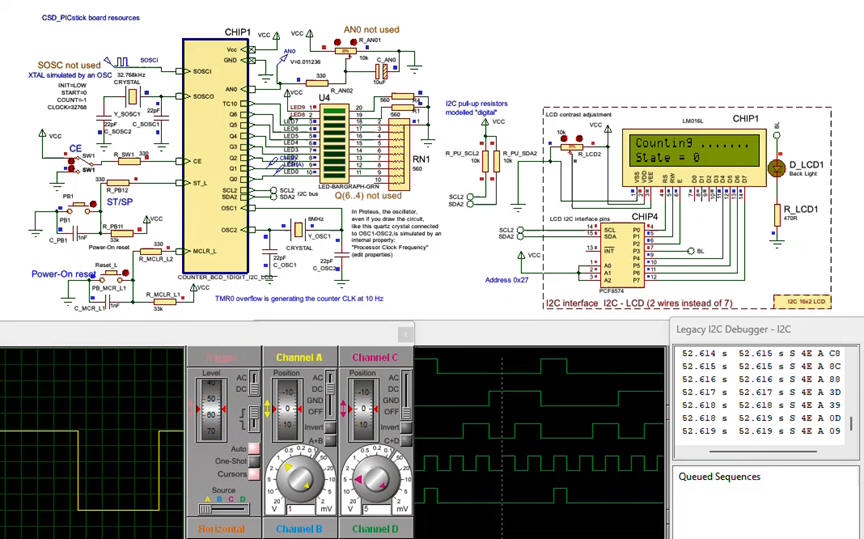 |
Fig. 6. This is video showing how the application can be monitored using the several instruments. The step mode of operation is also available to fix the watch window with important variables. |
| Specifications | Planning | Dev. & Test | 5. Prototype | Report |
Connecting the CSD_PICstick and programming the PIC18F46K22 is the simplest way to start prototyping and validating computer simulations.
The MPLAB SNAP programmer and in-circuit debugger allows further system checking and characterization. The I2C can be monitored using the VB8012 logic analyser.
Fig. 7. Photograph of the kit running. |
This is the final "Counter_BCD_1digit_LCD_prj.X.production.hex" that can be downloaded using the MPLAB IPE app.
| Specifications | Planning | Dev. & Test | Prototype | 6. Report |
In summary, we are able from now on, to interface to our basic CSD_PICstick for experimentation, a great deal of sensors and actuators based on the I2C interface.
A similar project can be started to generate another convenient library of functions to use the SPI bus.
Annex A1: I2C step #1: Connect a host and a client
Specifications
Learn the basics of I2C interface. Adapt the application note TB3281 to the PIC18F46K22 that we are using in the CSD_PICstick board. Generate an output port to write some LED values using the bus expander MCP23008 as an I2C client.
A) Planning hardware
The I2C host will be one of the two MSSP available in the microcontroller. Two wires and pull-up resistors are required. Because the microcontroller port C (MSSP1 SCL1 is RC3 and SDA1 is RC4) is used by the LED bar, we will use the MSSP2 peripheral as the I2C host: SCL2 is RD0, SDA2 is RD1.
In this tutorial we are simply liking to switch ON and OFF some LED connected to the port expander chip MCP23008 as shown in the technical brief from Microchip.
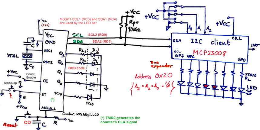 |
Fig. A1.1. I2C initial hardware. |
B) Planning software
Use the MCC Melody to generate the I2C stack of functions for the port expander peripheral. Compile and run in Proteus to check how it works. The idea is simply to add some instructions for turning on and off the LED
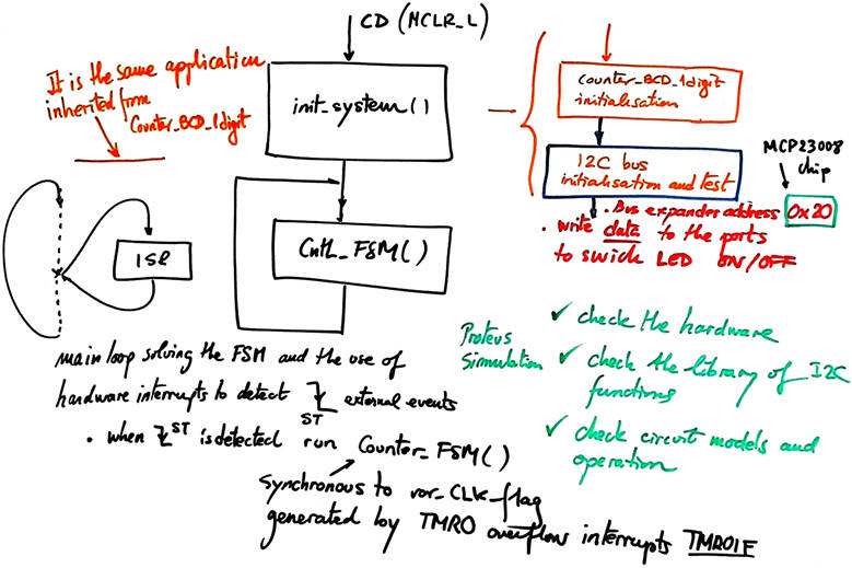 |
Fig. A1.2. To test the program, only the I2C initialisation and simple writing operations are required. |
Project location:
C:\DEE\LAB7\PIC18F\I2C_s1
A) Developing hardware
This is the Proteus hardware capture. We can include SPDT switches or jumpers to set the device address. And also the I2C debugger to monitor commands and data to the bus expander.
 |
Fig A1.3. Circuit captured in Proteus. Instruments will help to verify how does it operate. |
B) Developing software
Start a project using MPLAB v6.25 or newer and XC8 v3.00 or newer. Compile and run in Proteus to check how it works. Use Proteus 9.0 or newer to simulate the application. The idea is simply to add some instructions for turning on and off the LED The full project "I2C_s1.zip".
C) Step-by-step testing
We can take advantage of the I2C instrument to analyse the communication protocol.
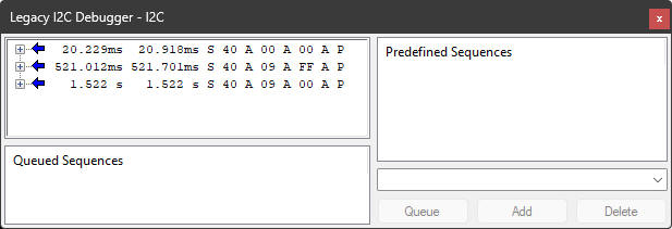 |
Fig A1.4. I2C commands and data. |
Annex A2: I2C step #2: Connect the PCF8574 I/O bus expander
Specifications
Add the I2C bus expander PCF8574 and run it using the MCC generated I2C library. Let us integrate the bus expander to the counter application; write the BCD number and the terminal count TC10 on the expanded port.
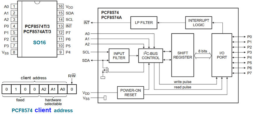 |
Fig. A2.1. PCF8574 port expander. |
A) Planning hardware
Add the I2C client PFC8574 to the same I2C bus. We select by hardware connections the address 0x27 (A (2..0) = "111"
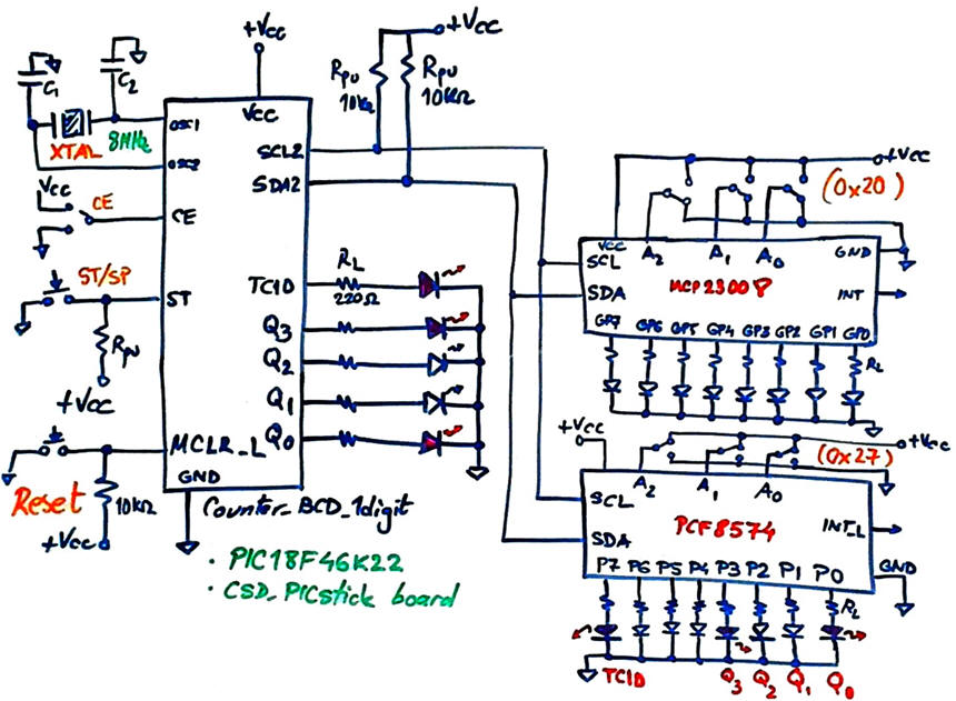 |
Fig. A2.2. The microcontroller host and two I2C peripherals. |
B) Planning software
We use the same I2C stack generated by MCC Melody in the previous annex.
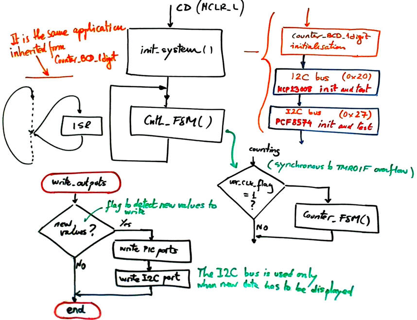 |
Fig. A2.3. Initialisation of the PCF8574 and also using it in write_outputs() function. |
Project location for this annex:
C:\DEE\LAB7\PIC18F\I2C_s2
A) Developing hardware
This is the Proteus hardware capture.
 |
Fig A2.4. Detail of the circuit captured in Proteus showing the two I2C clients for the same bus. |
B) Developing software
The full project "I2C_s2.zip".
C) Step-by-step testing
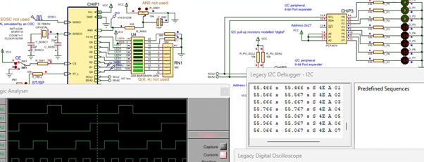 |
Fig. A2.5. BCD code and TC10 is represented as well on the port expander. Click to watch the recording. |
Annex A3: LCD step #1: LM016L and its library of functions
Specifications
The main objective of this tutorial develop the LCD library of functions through the I2C communication interface. Attach the I2C - LCD LM1602L kit to the same I2C bus. The kit, the schematic of which is shown in Fig. A3.1, includes the same bus expander PCF8574T to send commands and transmit and receive parallel data to the LCD controller Hitachi HD77480.
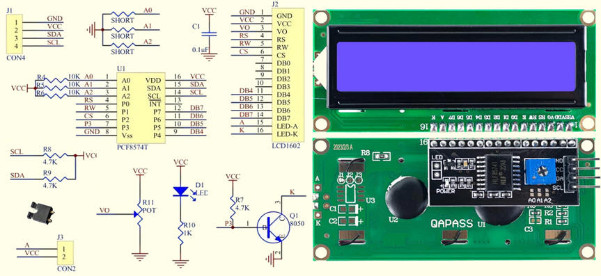 |
Fig. A3.1. Standard kit I2C to LM1602 (ref.). By default the short resistors are open circuits leaving A(2..0) = "111", thus, generating a 7-bit default client address '0x27'. |
A) Planning hardware
We continue the previous project adding the third I2C client for the same host managed by the microcontroller MSSP2.
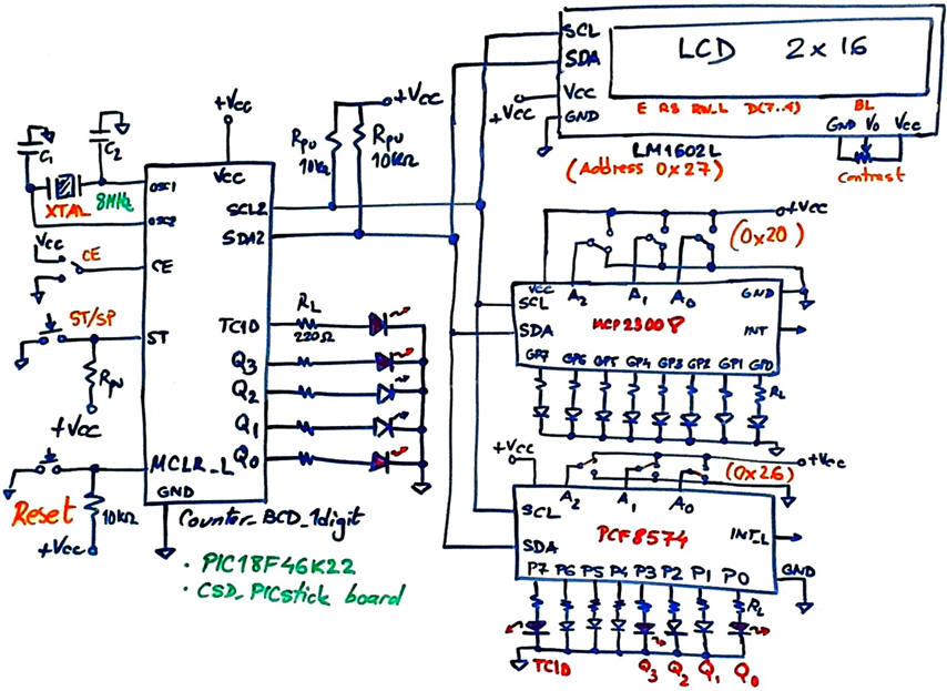 |
Fig. A3. 1. The microcontroller host and three I2C client peripherals. The PFC8574 interface is soldered to the parallel the LCD board. |
B) Planning software
Basically, we need to specify as definitions the commands described in the LCD controller datasheet, Fig. A3.2.
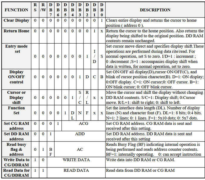 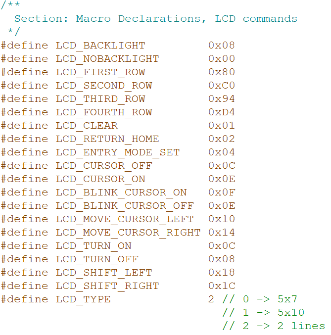 |
Fig. A3.2. List of commands and defines. |
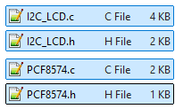
Our project will include the headers and the source files for both the basic I2C instructions and the LCD interface,
Our library will write to the bus expander using the MCC Melody I2C stack. We need to adapt a similar existing one, for instance, from this ref1.
 |
Fig. A3.3. Operations to test some of the LCD library functions. |
Our tutorial will end verifying that we are capable to write ASCII characters to the display, the classic "Hello World".
Project location for this annex:
C:\DEE\LAB7\PIC18F\LCD_s1
A) Developing hardware
This is the Proteus hardware capture.
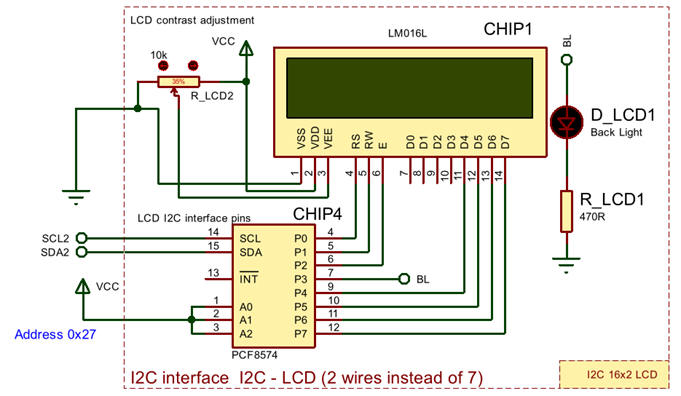 |
Fig. A3.4. Detail of the circuit captured in Proteus. |
B) Developing software
The full project "LCD_s1.zip" and the LCD and I2C libraries "I2C_LCD_1602A_kit.zip" to be compiled in the same project.
C) Step-by-step testing
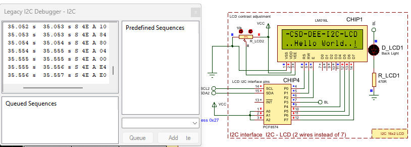 |
Fig. A3.5. Some commands and data from the I2C analyser when writing "Hello World" to the LCD. |
From this tutorial and using a similar systematic approach, we can go ahead creating other professional applications based on FSM and including, buttons, switches, keyboards, LCD, LED, motors, A/D, etc.
| Home Term 26/27-Q1 Contact Products Electronic devices and companies Software Books Magazines Instruments DEE Library EETAC DEEL |

|
|
| Web activa des de 09/2001, @ F. J. Robert, Web editat amb Microsoft Expression Web 4. El contingut és un complement als materials d'estudi del curs Circuits i Sistemes Digitals disponibles al campus digital Atenea. Llicència:Reconeixement 4.0 Internacional de Creative Commons |