

|
Bachelor's Degree in Telecommunications Systems and Network Engineering |

|
Chapter 2 problems |
- D2.14 - |
Traffic light controller (version 2) (FPGA-VHDL) |
1. Specifications
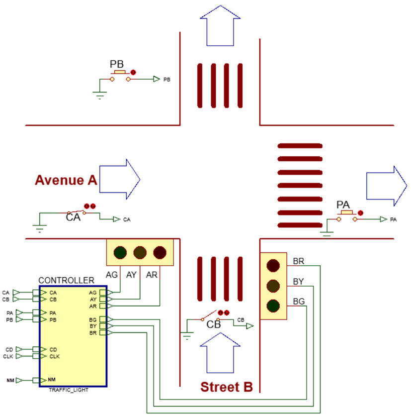
Design a traffic light controller for the given street intersection in Fig. 1. We aim to implement a kickoff project including some of the listed features, but not all of those described in the traffic light tutorial. We also organise several design steps and phases to make the design and conception easier.
The same project designed for programming a μC is in D3.14.
 |
|
Fig 1. Street intersection to be controlled by our Traffic_light system. The sequence includes the the security all-red clearance intervals. |
Find information on the internet on the green/yellow/red traffic light sequence currently used in Europe. Or simply observe a real traffic light intersection and deduce its operating sequence. We can imagine the six states shown in Fig. 1. Complete your research by finding typical colour times for four-way intersections according to approach speed, vehicle length, and street width.
The night-mode NM signal may originate from a daylight sensor or an auxiliary clock. When NM = '0' (daytime), the standard traffic light sequence operates continuously. When NM = '1' (night), both light poles display intermittent 1 Hz yellow lights, and the vertical pole STOP signs are activated at the intersection.
Draw an example of a timing diagram considering only the control signal NM.
NOTE: The idea is to read and study as many materials, books, examples or advanced tutorials, but do not copy from them. You aim to imagine that this project is derived from the LAB6 tutorial, where we organised an FSM-controlled light switch. The better you comprehend the laboratory tutorial, the faster you will design this application.
2. Planning phases and steps
Design phase #1: An FSM to generate the traffic light sequence
In this initial design phase, we will apply our FSM recipe. This architecture is translated to VHDL as a Plan C1 single file where the three main components are processes.
Step #1: Implement the basic traffic light sequence, including only the switch NM.
Logically, in a real traffic light controller, the time duration of each colour pattern in Avenue A and Street B is programmed or configured by technicians or the authorities in charge of road networks. Here, especially in this first design phase, we will simply consider that there is a new colour pattern every CLK period.
Project location: C: /CSD/P6/Traffic_light/(files)
Propose a state diagram. During nighttime operation, the yellow outputs from the FSM are irrelevant, as the lamps are controlled by the multiplexers switched to a 1 Hz square wave.
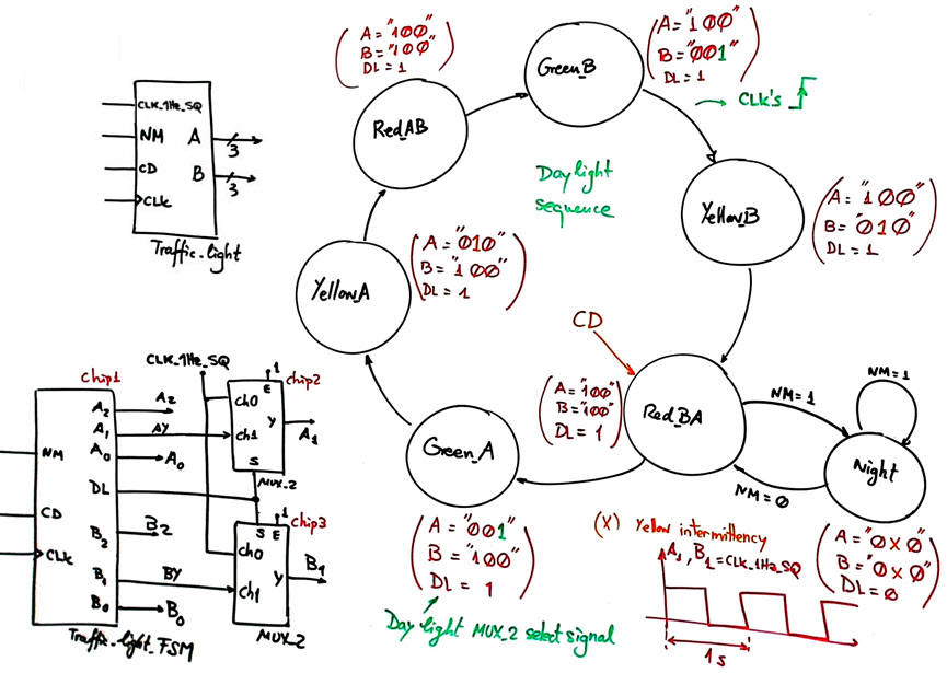 |
| Fig. 2. Traffic light controller symbol and state diagram for design phase #1. |
To implement Chip1, adapt the FSM architecture to this problem, naming and connecting all signals, inputs, and outputs.
Draw the state register memory based on D_FF and deduce the number of D_FF required when encoding the machine using the following options:
Option #1: radix-2 (sequential)
Option #2: Gray
Option #3: Johnson
Option #4: one-hot
Draw the CC2 truth table to obtain the circuit's outputs and its equivalent flowchart behavioural interpretation (plan B).
Draw the CC1 truth table to obtain the circuit's state transitions and its equivalent flowchart behavioural interpretation (plan B).
Write the FSM VHDL file.
Start a Quartus Prime synthesis project for one of the following programmable target chips:
Option #1: Cyclone IV EP4CE115F29C7
Option #2: MAX II EPM2210F324C3
Option #3: MAX 10 10M50DAF484C7 (*)
(*) Remember that this chip does not generate sdo delay files; thus, use another one when gate-level simulations are required.
Inspect and annotate the RTL and technology views. Check the number of D_FF synthesised in this application.
Generate a VHDL testbench fixture schematic using two CLK signals.
 |
|
Fig. 3. Testbench fixture. What inputs, outputs and internal signals are to be monitored? |
Run functional simulations to verify your design. Visualise as well in the wave timing diagram the internal states.
Run gate-level simulations to measure the propagation time CLK to output (tCO). Measure the minimum TCLK period or the maximum frequency of operation of the FSM.
NOTE: Step #2 or design phase #2 should not be initiated until Step #1 is fully completed and confirmed to be functionally operational (1-2-3-4).
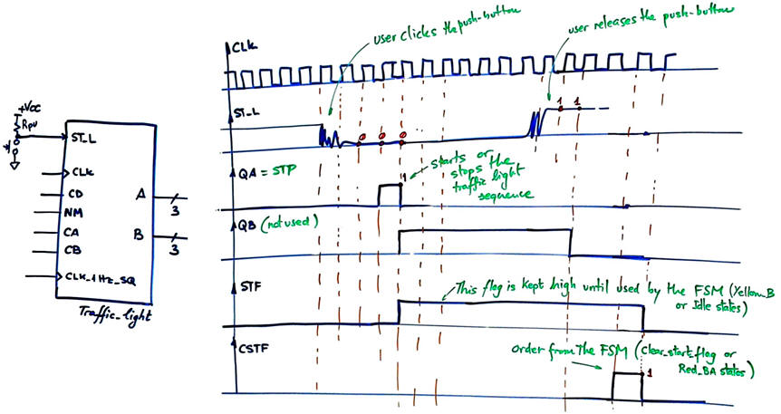
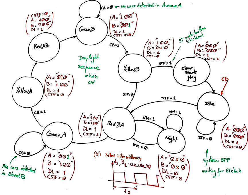
Step #2: Add a start/stop control pushbutton (ST_L) and street vehicle sensors (CA and CB) to interrupt the normal traffic-light sequence when no vehicles are detected on a given street. If no vehicles are detected on Street B, there is no need to stop traffic on Avenue A; therefore, traffic on Avenue A may continue to proceed under a green signal. Vehicle sensors are typically embedded beneath the pavement near the intersection.
 |
|
Fig. 4. The new symbol including the car sensors and the start/stop push-button. |
  |
|
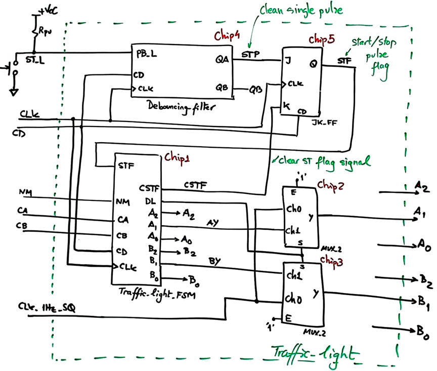
Fig. 5. Example of how the schematic and the state diagram may be modified to include the new control signals ST, CA and CB. Clicking ST starts operations; clicking it again stops the system, turning off all lights: A = B = "000". Technicians may push the start/stop button any time; thus, this event must be saved by a flip-flop as a flag (STF). It can be cleared (CSTF = 1) once used by the FSM to start or stop the light sequence. Pressing and releasing mechanical push-buttons always generate noisy signals that can be filtered by our Debouncing_filter. |
Project location:
C:/CSD/P6/Traffic_light2/files)
Step #3 (optional): Add PA and PB push-buttons to allow pedestrians to cross the intersection at any time when the traffic light sequence is locked in a given street because there are no cars in the other.
Design phase #2: Programmable timer to adjust red/yellow/green light times
To make a commercial equipment, we must complete the traffic light by adjusting the time for each colour code.
Option #1: Green_B: 70 s; Yellow_B: 5 s; Red_BA or Red_AB: 1.5 s; Green_A = 80 s; Yellow_A: 6 s
Option #2: Green_B: 60 s; Yellow_B: 4 s; Red_BA or Red_AB: 1.2 s; Green_A = 70 s; Yellow_A: 5 s
Option #3: Green_B: 90 s; Yellow_B: 5.6 s; Red_BA or Red_AB: 1.4 s; Green_A = 100 s; Yellow_A: 7.5 s
We invent a programmable timer to fix the five timing periods as the dedicated processor in P8 or D2.21. Fig. 7 shows an example of internal architecture. The main idea is to accommodate the trigger TG signal duration to the timer T_CLK.
|
|
|
Fig 6. The new symbol for the traffic light controller. |
|
Fig 7. The dedicated processor building blocks. |
Project location:
C:/CSD/P7/Traffic_light/files)
Design phase #3: CLK_Generator
Design the CLK generator circuit from a 50 MHz quartz crystal oscillator to obtain all the clocking signals required to drive the traffic light application: debouncing filter push-button sampling frequency fS_CLK = 220 Hz; system and programmable counter frequency: fSYS_CLK = 22 Hz; yellow intermittency frequency: 1Hz
Deduce the number of D_FF that the full project Traffic_light will require.
Project location:
C:\CSD\P8\Traffic_light\(files)
| Home Term 26/27-Q1 Contact Products Electronic devices and companies Software Books Magazines Instruments DEE Library EETAC DEEL |

|

|
| Web activa des de 09/2001, @ F. J. Robert, Web editat amb Microsoft Expression Web 4. El contingut és un complement als materials d'estudi del curs Circuits i Sistemes Digitals disponibles al campus digital Atenea. Llicència:Reconeixement 4.0 Internacional de Creative Commons |