|
|
Bachelor's Degree in Telecommunications Systems and in Network Engineering |
|
Chapter 2 problems |
- D2.11 - |
Wireless IR TV remote control (FPGA-VHDL) |
1. Specifications
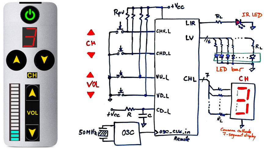
We want to design a simple TV remote as shown in Fig. 1. To simplify it, only channel and volume selection will be implemented. Its internal architecture is based on channel and volume code generators of 4-bit binary combinations (chip1 and chip2), a Hex_7seg_decoder (Chip3), and the IR light transmitter Serial_TX (Chip4).
The same project designed programming a μC is in proposed in D3.11.
 |
|
Fig. 1. Remote control symbol and schematic. |
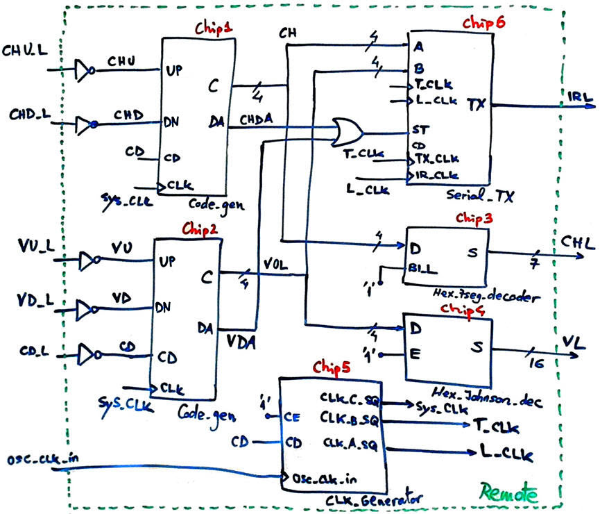
We will propose a Plan C2 hierarchical design based on components as represented din Fig. 2. A first design phase we will implement code generators and decoders. The Code_gen produces a data available (DA) pulse when a new value is generated. This flag is used by the Serial_TX to start the transmission. In a second design phase we can add the CLK_Generator. and finally, in a third design phase we can complete the Remote circuit connecting the Serial_TX to drive the infra-red LED.
 |
|
Fig. 2. Internal architecture. |
2. Planning
Design phase #1: Basic features: Counter, LED bar and 7-segment decoders.
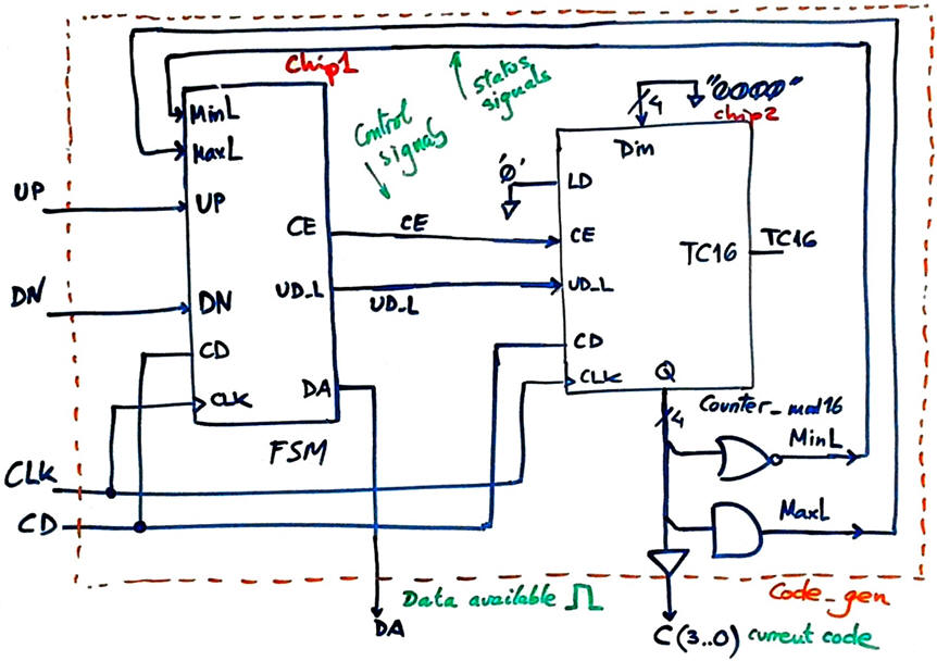
The idea of the chip Code_gen is represented in Fig. 3. The FSM drives a standard Counter_mod16 (Chip2) up and down when buttons UP or DN are pressed. When the count reaches minimum "0000" clicking the DN button has no effect. Likewise, on maximum value "1111", clicking button UP has no effect.
 |
|
Fig. 3. Proposed architecture for the chip Code_gen. This is a very simple dedicated processor where the datapath is a standard Counter_mod16 and the control unit is the Chip1 FSM. It is intended to keep the code or increment or decrement it every time that the push-buttons are pressed. |
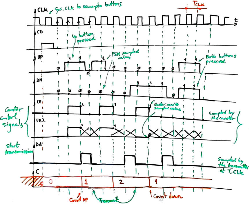
Timed signals are represented in Fig. 4. When the user clicks a button, output CE = '1' for a single CLK period to increment or decrement only one counter value; When CE = '0' the value of the output UD_L does not care. When the two buttons are clicked simultaneously the counter does nothing, thus keeping the current value as when no one is clicking the buttons. When the data available flag is set, the Serial_TX can capture and transmit the counter's number at the specified transmission frequency.
 |
|
Fig. 3. Example waveforms for the FSM Chip1 that shows how control signals CE and UD_L are generated depending on the buttons pressed. The key point is that only one synchronous pulse is generated even if the button is kept clicked for a long time ('long time' here in this context means many CLK periods, which is the usual situation). |
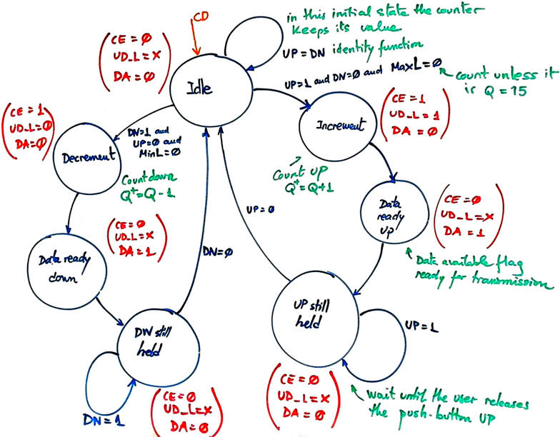
Infer and draw the FSM state diagram. Annotate all the state transitions and outputs. Fig. 4 shows how it may be conceived.
 |
|
Fig. 4. Example of state diagram to control the push-buttons and counting up or down. |
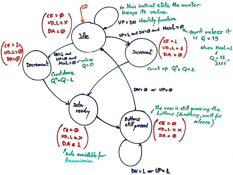
Indeed, the state diagram in Fig. 4 can be simplified as shown in Fig. 5, because some states are equivalent for the purpose of controlling the counter or triggering the dada available flag.
 |
|
Fig. 5. Second state diagram version. When Idle, the counter keeps the number Q. |
Adapt the FSM architecture to this problem, naming and connecting all signals and inputs and outputs.
Draw the state register memory and deduce the number of D_FF required when encoding the machine using one of the following options:
Option #1: radix-2 (sequential)
Option #2: Gray
Option #3: Johnson
Option #4: one-hot
Draw the CC2 truth table to obtain the circuit's outputs and its equivalent flowchart behavioural interpretation (plan B).
Draw the CC1 truth table to obtain the circuit's state transitions and its equivalent flowchart behavioural interpretation (plan B).
Project location:
C:\CSD\P6\remote\(files)
Write the FSM VHDL file.
Complete the top architecture Code_gen in Fig. 2 without including Chip5 and Chip6. Get the Counter_mod16 VHDL code from its tutorial and build the complete top Code_gen project. Find or design the decoders for the 7-segment display and the LED bar.
Start a Quartus Prime synthesis project for one of the following programmable target chips:
Option #1: Cyclone IV EP4CE115F29C7
Option #2: MAX II EPM2210F324C3
Option #3: MAX 10 10M50DAF484C7 (*)
(*) Remember that this chip does not generate sdo delay files, thus use another one when gate-level simulations are required.
Inspect and annotate the RTL and technology views. Check the number of D_FF synthesised in this application.
Generate a VHDL testbench fixture schematic. Translate the timing diagram sketch from the specifications into de corresponding stimulus processes.
Run functional simulations to verify your design. Visualise as well in the wave timing diagram the internal states.
Run gate-level simulations to measure the propagation time CLK to output (tCO). Measure the minimum TCLK period or the maximum frequency of operation of the FSM.
Design phase #2: CLK_Generator
Design the CLK generator circuit from a 50 MHz quartz crystal oscillator to obtain all the clocking signals required to drive the application. Deduce the number of D_FF required for this component. Add this Chip5 to the top architecture and check the three generated CLK signals.
Project location: C:\CSD\P7\remote\(files)
The options for the system CLK are:
Option #1: fSYS_CLK = 230 Hz; fT_CLK = 9.6 kHz; fL_CLK = 57.6 kHz
Option #2: fSYS_CLK = 260 Hz; fT_CLK = 7.2 kHz; fL_CLK = 50.4 kHz
Option #3: fSYS_CLK = 185 Hz; fT_CLK = 4.8 kHz; fL_CLK = 43.2 kHz
Design phase #3: Serial_TX
(Optional, only if you have spare time and the design phases #1 and #2 works correctly).
Binary codes into IR light? Designing such block is a new interesting project where you can learn about frequency, pulse width or pulse duration modulations. You can also learn about its dual Serial_RX block located in the TV set to convert light back into 4-bit binary codes.
Firstly, we can imagine that the transmitter will serialise the 8-bit parallel information [A(3..0), B[3..0)] (examples at USART, Serial_transmitter). Secondly, it will modulate the Serial_out to drive an infrared (IR) LED adopting a given industrial modulation standard. Some references to study: 1, 2, 3, 4, 5, 6, 7, 8, 9, 10.
Project location: C:\CSD\P8\remote\(files)
Optional. Other additional features:
As it is now, when clicking the button the code increments or decrements one number. How can you implement this functionality: if the button is pressed longer than 2 seconds, the channel count goes up or down at 3 Hz rate until the button is released (most commercial remotes work in this way). Thus, sequencing the 16 codes will be possible in two ways: clicking with a short click the button 16 times or instead keeping the button pressed for 5 s.
How to add to the remote control an ON/OFF button to turn on and off the TV set?
| Home Term 26/27-Q1 Contact Products Electronic devices and companies Software Books Magazines Instruments DEE Library EETAC DEEL |

|
|
| Web activa des de 09/2001, @ F. J. Robert, Web editat amb Microsoft Expression Web 4. El contingut és un complement als materials d'estudi del curs Circuits i Sistemes Digitals disponibles al campus digital Atenea. Llicència:Reconeixement 4.0 Internacional de Creative Commons |