|
|
Bachelor's Degree in Telecommunications Systems and in Network Engineering |
|
Chapter 2 problems |
- D2.7 - |
Dumbwaiter or simple lift (FPGA-VHDL) |
1. Specifications
Design phase #1: basic FSM
Our company has to design the control system for a simple dumbwaiter (a small freight lift used to transport food, wine, and other items between floors of a building). It will transport loads between a 2-level kitchen. Fig. 1 shows a photograph of an installed commercial dumbwaiter and a detail of the motor and the control system installed under the car.
The same project designed programming a μC is in D3.7.
 |
| Fig. 1. Photograph of a commercial window dumbwaiter and its motorised car. |
Some questions and ideas to kick off the project and organise it in five sections. Apply the FSM architecture to this problem.
Firstly draw a sketch of the dumbwaiter system including up and down buttons for both levels, location of the floor sensors, green and red LED's, and outputs for driving the stepper motor. See Fig. 2.
 |
| Fig. 2. Sketch of the 2-level dumbwaiter indicating sensors, pushbuttons and output functions to drive the stepper motor and the LED. |
We can open this "Dumbwaiter_pre_circuit.pdsprj" (place this executable "picstepr.hex" at the same folder) to figure out how it may be running. The stepper motor controller is in itself another project as proposed in D2.2.
Sensors and buttons:
- U1, D1, U0, D0: buttons for calling the car.
- LS1, LS0: limit switches to detect the presence/absence of the car stopped at each floor.
Special signals:
- CD: if pressed by a technician, or after power on, this special signal takes the car from its current location to the level 0, the initial state).
- CLK: For sampling button values and synchronising the FSM.
Outputs for controlling the car motor:
- INH: when high this signal inhibits the motor movement.
- UD_L: when INH is not asserted, this signal generates up movement when high and down movement when low.
Additional visual outputs:
- GL1, RL1, GL0, RL0: LEDs for indicating operation: green LED is ON when the car is stopped in the corresponding level, red LED is ON when the car is moving between floors.
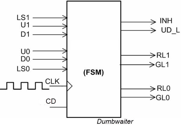
Secondly, draw the symbol of the entity to be designed.
 |
|
Fig. 3. Symbol. |
It is a good idea at this point, to discuss what logic levels to consider from the push-buttons and switches. For instance, LS1 and LS0 will never be '1' at the same time. Both will be '0' when the car is in transit between levels. If the car is at level 1, clicking U1 will have no effect (don't care), and when the car is stopped at level 0, clicking D0 has no effect. When the car is in transit, clicking buttons has no effect.
Sketch a timing diagram showing the main operations on how the machine works.
 |
| Fig. 4. Example timing diagram. |
2. Planning ideas for the design phase #1
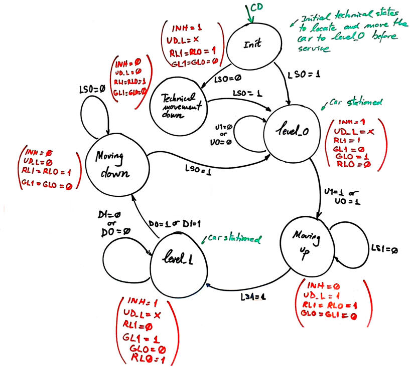
Infer and draw the state diagram. Annotate state transitions and outputs. We can start imagining that due to a power outage supply failure or a disruption in electricity supply, the car may be stopped in any floor or in between stories, a technical CD signal is required to initialise the machine moving down and station the car at level 0.
Fig. 5 state diagram works supposing that push-buttons and limit sensors are filtered using circuits such the debouncing_filter FSM, generating clean digital pulses when pressed.
 |
|
Fig. 5. Example of state diagram to start discussing on the problem. |
Adapt the FSM architecture to this problem, naming and connecting all signals and inputs and outputs.
Draw the state register memory based on D_FF and deduce the number of D_FF required when encoding the machine using the following options:
Option #1: radix-2 (sequential)
Option #2: Gray
Option #3: Johnson
Option #4: one-hot
Draw the CC2 truth table to obtain the circuit's outputs and its equivalent flowchart behavioural interpretation (plan B).
Draw the CC1 truth table to obtain the circuit's state transitions and its equivalent flowchart behavioural interpretation (plan B).
Project location:
C:\CSD\P6\dumbwaiter\(files)
Write the FSM VHDL file.
Start a Quartus Prime synthesis project for one of the following programmable target chips:
Option #1: Cyclone IV EP4CE115F29C7
Option #2: MAX II EPM2210F324C3
Option #3: MAX 10 10M50DAF484C7 (*)
(*) Remember that this chip does not generate sdo delay files, thus use another one when gate-level simulations are required.
Inspect and annotate the RTL and technology views. Check the number of D_FF synthesised in this application.
Generate a VHDL testbench fixture schematic. Translate the timing diagram sketch from the specifications into de corresponding stimulus processes.
 |
|
Fig. 6. Testbench fixture. What inputs, outputs and internal signals are to be monitored? |
Run functional simulations to verify your design. Visualise as well in the wave timing diagram the internal states.
Run gate-level simulations to measure the propagation time CLK to output (tCO). Measure the minimum TCLK period or the maximum frequency of operation of the FSM.
Design phase #2: FSM + datapath
In order to get an estimation of the dumbwaiter usage and duty, add operational resources to count the number of complete cycles that the machine runs every day. After 100 cycles an overflow flag OV pulse will reset the counter and trigger a 1.3 kHz sound wave for 2.5 s. The current cycle count is represented in 7-segment displays.
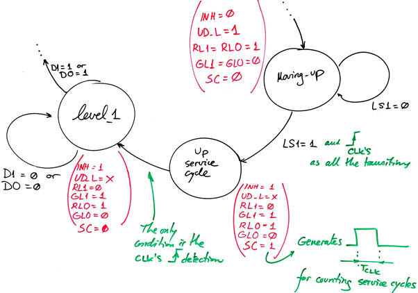
For this industrial machine, a complete service or duty cycle, is moving from the stationary level 0 to level 1 or vice versa. In this way, we need to add an extra state after leaving moving_up and another one after leaving moving_down to generate a synchronous single pulse to drive the cycles counter.
 |
|
Fig. 7. The additional state Up_service_cycle generates a single CLK period pulse SC after having reached the level 1. |
Project location: C:\CSD\P7\dumbwaiter\(files)
Design phase #3: CLK_Generator
Design the CLK generator circuit from a 50 MHz quartz crystal oscillator to obtain all the clocking signals required to drive the application. Deduce the number of D_FF that the full project dumbwaiter will require.
Project location: C:\CSD\P8\dumbwaiter\(files)
The options for the system CLK are:
Option #1: fCLK = 95.7 Hz
Option #2: fCLK = 126.7 Hz
Option #3: fCLK = 237.6 Hz
How to drive the two red LED intermittently at 2 Hz when the car in transit between stories?
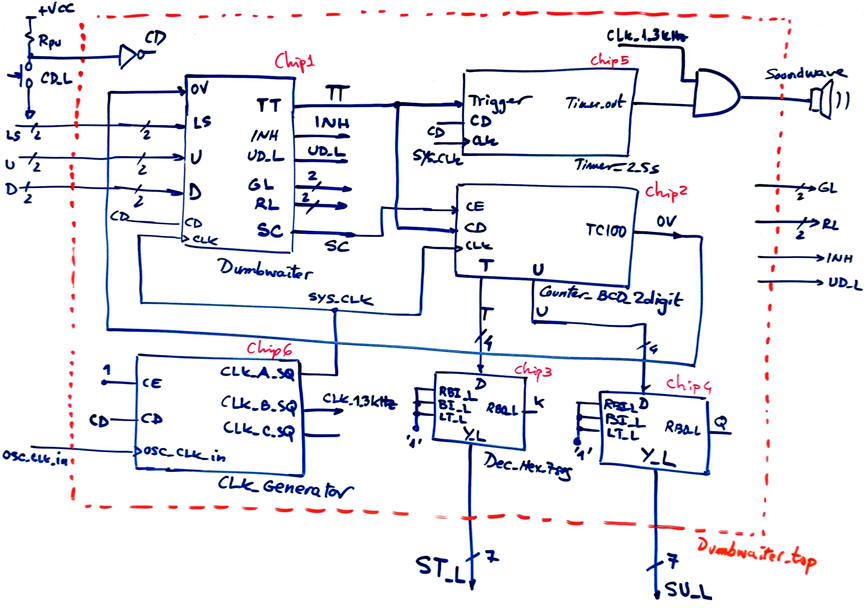
An initial internal schematic to figure out how to organise the phase #2 and phase #3 schematics is presented in Fig. 7. Discuss the circuit and modify it when necessary. For instance, another CLK_3Hz may be used for flashing intermittently the red LED when in transit.
 |
|
Fig. 7. The idea of the Dumbwaiter_top. |
You can adapt the timers from this D2.21 version A.
Optional: A security enhancement for preventing user accidents can be added in yet another new design phase. Install sensors switches (DS1, DS0) and electric drop bolt locks (DL1, DL0) in the level doors, so that the car does not move unless doors are closed, and they do not open while the car is in transit or not yet stopped in the corresponding level.
 |
|
Fig. 67 Example of a level door secured with an electric drop bolt lock (ref.). The idea is to keep the level doors closed while the car is in transit and inhibiting car movements while doors are open. |
| Home Term 26/27-Q1 Contact Products Electronic devices and companies Software Books Magazines Instruments DEE Library EETAC DEEL |

|
|
| Web activa des de 09/2001, @ F. J. Robert, Web editat amb Microsoft Expression Web 4. El contingut és un complement als materials d'estudi del curs Circuits i Sistemes Digitals disponibles al campus digital Atenea. Llicència:Reconeixement 4.0 Internacional de Creative Commons |