|
|
Bachelor's Degree in Telecommunications Systems and in Network Engineering |
|
Lecture 2 |
L6.2: FSM applications [P6] Designing a 16-key matrix encoder |
[10 Nov] |
NOTE: To review and resume ideas on flip-flops, start this lecture having solved the question at the bottom the last lecture L5.3
NOTE: To review the main ideas behind a FSM and how to design them, start this lecture on the design of a keypad encoder having solved the question at the bottom the last lecture L6.1 and also studied the design sequence presented in the LAB6 tutorial.
2.6.3. Keyboard scanning: Matrix_encoder_16key
Let's study and run the tutorial on the design of the 16-key matrix keyboard encoder specified in our highlighted P6. As you can imagine, our FSM procedure will be used.
The reset button or an initial user action is not required because the Power-ON reset circuit allows system initialization after connecting the circuit to the power supply.
- Specifications and plan: Example of a commercial chip, matrix keypad simulated in Proteus, matrix circuit in rows and columns, project symbol and inferred state diagram. FSM organisation, CLK frequency for matrix keyboard scanning speed, state register, CC1 and CC2 truth tables and flowcharts.
- Development and test. VHDL file following the FSM pattern, EDA tool project and synthesis, RTL circuit, technology circuit, testbench preparation, functional simulation, gate-level simulation.
This is a keypad scanner commercial chip from Dialog (Renesas) a company specialised in asynchronous state machines (ASM) architectures similar to the systems we are dealing with. In P12 we can implement again the the functionality of the keypad scanner programming a PIC microcontroller, PORTB generates special interrupts for easy connecting keypads.
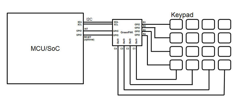 |
Fig 1. Keypad scanner from Dialog (Renesas). Block diagram of the GreenPAK chip application that performs the I2C interface between a keypad and a microcontroller. |
Prototype demonstration. This project is enhanced using materials from P8 on the design of the CLK_generator component so that scanning frequency can be derived from a quartz crystal oscillator populating the training board.
Other materials of interest (theory and commercial examples):
At this stage it is recommended to read books in digital electronics to see how content on sequential systems is explained and discuss and compare with our CSD methodologies.
An application note on how to design safe FSM, the concept to prevent that a machine "hangs" being unable to get back to a valid state.
Other examples of FSM applications are listed in products page.
Activity #1:
Examine the Matrix_encoder_16key RTL file once the circuit is synthesised and answer the questions in Atenea.
Activity #2: This is the internal architecture of the MM74C922 chip. Deduce the signals and outputs Q(4..0) when clicking several keys, for example 1, 5, 14, 15, 16.
Which blocks are sequential circuits? Which blocks are combinational?
How to implement the memory register in VHDL as a single component Mem_reg_5bit using plan B and plan C2?

| Home Term 26/27-Q1 Contact Products Electronic devices and companies Software Books Magazines Instruments DEE Library EETAC DEEL |

|
|
| Web activa des de 09/2001, @ F. J. Robert, Web editat amb Microsoft Expression Web 4. El contingut és un complement als materials d'estudi del curs Circuits i Sistemes Digitals disponibles al campus digital Atenea. Llicència:Reconeixement 4.0 Internacional de Creative Commons |