|
|
Bachelor's Degree in Telecommunications Systems and in Network Engineering |
|
Chapter 3 problems |
- D3.12 - |
Electronic roulette (µC - C) |
1. Specifications
Let us design an electronic roulette using a µC chip. After turning on the power supply, a 5 V battery, the roulette inicialises showing number 0. To bet, the user clicks and holds pressed the play (P_L) button, while the 7-segment displays shows random numbers until the P_L is released and the new bet is displayed. The circuit keeps the last bet LED lighting until a new bet is started.
The same project designed using hardware is stated in D2.12. The only difference is that we have added two 7-segment displays to the 37-LED. The architecture corresponds to a dedicated processor, where a FSM is in charge of controlling the play push-button and also pooling a modulo-37 counter to generate a random number.
The design phase #1 will include an external Counter_mod37 chip. The FSM will read at CLK2 rate the current counter radix-2 value, once the P_L push-button falling edge is detected by means on an external interrupt.
The design phase #2 will add an LCD screen to represent textual and numerical information and thus, be able to replace both, the 7-segment displays and also the LED wheel.
In the design phase #3, the external Counter_mod37 will be replaced and implemented using TMR2 internal peripheral.
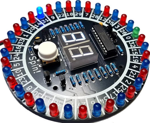
Fig. 1 shows a typical kit from the Electronic Kit Shop. To simplify and design the circuit in several stages, we will not include in this first phase the 37-LED; only the two 7-segment displays.
  |
|
Fig. 1.Example commercial roulette kit (ref. pdf). Initial electronic circuit that does not included the 37-LED. |
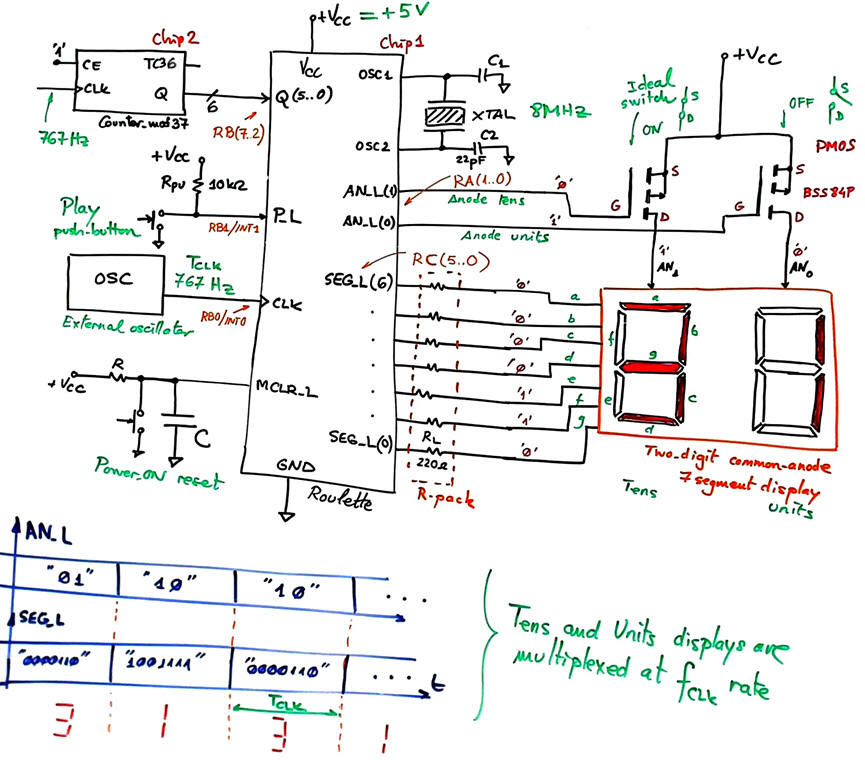
The external 767 Hz CLK will trigger interrupts to synchronise the FSM. For instance, this frequency is used for multiplexing the tens and units information for the 7-segment displays.
Optional. Another approximation to the problem for you to study, will be replacing the external hardware counter by the rand() and srand() C functions from the standard <stdlib.h> library. It is very interesting at this point to read the many applications that random number generators (RNG) have in engineering.
2. Planning
Let us build this device organising several design phases and several steps within each phase. Fig. 2 shows an initial state diagram for displaying the bet, and also for displaying some activity while the used is playing. After a system reset, the digits are displaying "00". This situation is kept until the user clicks the P_L button.
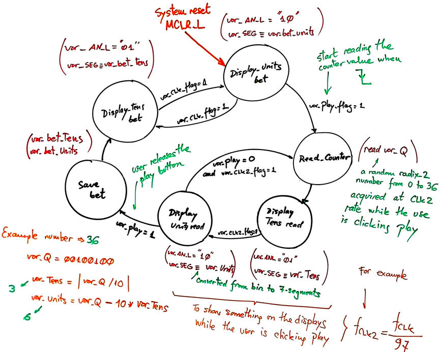 |
Fig. 2. Proposed state diagram for the FSM. |
Design phase #1: basic features.
Solve the circuit for the design step #1. Only when it is fully tested working correctly and reported, solve the (optional) design step #2 or continue with the design phase #2.
- Design step #1: Basic features with play button, external counter and multiplexed 7-segment displays
Project location:
C:\CSD\P10\Roulette\(files)
Project source files: "Roulette.pdsprj", "Roulette.c", "config.h"
a) Draw the hardware schematic necessary for step #1 simplifying Fig. 1: external oscillator, AN_L and SEG_L outputs, Q input, reset circuit MCLR_L, and an 8 MHz quartz crystal oscillator. How to configure the inputs and outputs in init_system(). Use the suggested port connections.
This is a Proteus circuit example "Roulette.pdsprj" inherited from LAB10 tutorial Counter_BCD_1digit. It contains a version of a Counter_BCD_mod36 adapted from lecture L7.3 on counter expansion and truncation. It can run freely at any arbitrary large frequency such 767 Hz and be read at the µC port pins RB(7..2). The circuit also includes the 7-segment displays from B3.7. to start the development, we recommend to save the source code from the LAB10 tutorial Counter_BCD_1digit as "Roulette.c", compile and attach it to this hardware.
What pins will be read? How many external interrupts are required for this step#1?
b) Draw an example of state diagram (as in Fig. 2) indicating state transitions and outputs. What example tutorial can be used as a model to copy and adapt?
c) Draw the hardware/software diagram indicating the required RAM variables and how the FSM is solved in software.
d) Draw the truth tables and their equivalent flowcharts for state_logic() and output_logic() functions.
e) What is the interrupt service routine ISR() used in this application? Draw its flowchart. The var_CLK2_flag is also implemented in the ISR().
f) Develop and test (debugging) the project capturing the hardware circuit in Proteus and writing the C source code. You must use the watch window to monitor RAM variables from the very beginning.
- Design step #2: (optional) Study how to connect 37 LED to microcontroller ports to represent the roulette wheel, as shown in Fig. 1 commercial kit photograph.
Inherit the step #1 source hardware and software files into the new project location:
C:\CSD\P10\Remote2\(files)
Project source files: "Remote.pdsprj", "Remote.c", "config.h"
a) Complete the hardware schematic for step #2 (Fig. 1).
Explain what is new in sections b), c), d), e), f)
Develop and test the new feature.
Let us add an LCD display as studied in P11 to this application. The idea is to use ASCII characters to represent the current bet and also some dynamic patterns while the user is playing, thus, replacing the 2-digit multiplexed system, and even the 37-LED wheel.
Project location:
C:\CSD\P11\Roulette_LCD\(files)
Project source files: "Roulette_LCD.pdsprj", "Roulette_LCD.c", "config.h", "lcd.c", "lcd.h"
g) Enhance the schematic from the previous design phase #1 to include an LCD attached to port D (6-bit used) as studied in tutorials. Remove the 2-digit multiplexed display.
h) Enhance the software and the source file to drive the LCD.
In this design phase you can learn the LCD interface step by step. For instance:
- Design step #1: Print ASCII messages on the LCD. For instance "Click Play to bet", "Bet = 6", etc.
- Design step #2: Print numeric information, for example "Random numbers = *", where "*" are different numbers generated while the user is clicking the play button.
Develop and test the new feature.
Design phase #3: Using TMR2 peripheral subsystem.
The 767 Hz external CLK used to visualise the bet on the multiplexed displays and also for pooling the random number from the counter, is replaced by the internal 8-bit TMR2 peripheral to generate interrupts (TMR2IF) every TP = 1.304 ms. Discuss the hardware features of this peripheral and its applications. The external INT0 will be no longer required.
Project location:
C:\CSD\P12\Roulette_LCD_TMR2\(files)
Project source files: "Roulette_LCD_TMR2.pdsprj", Roulette_LCD_TMR2.c", "config.h", "lcd.c", "lcd.h"
Develop and test the new feature.
Optional. Solve the roulette applications using rand() and srand() C functions from the standard <stdlib.h> library. Discuss its advantages and drawbacks.
| Home Term 26/27-Q1 Contact Products Electronic devices and companies Software Books Magazines Instruments DEE Library EETAC DEEL |

|
|
| Web activa des de 09/2001, @ F. J. Robert, Web editat amb Microsoft Expression Web 4. El contingut és un complement als materials d'estudi del curs Circuits i Sistemes Digitals disponibles al campus digital Atenea. Llicència:Reconeixement 4.0 Internacional de Creative Commons |