|
|
Bachelor's Degree in Telecommunications Systems and in Network Engineering |
|
| | ||
SP2_1: Gate-level measurements (how fast is a circuit calculating?) |
||
| NOTE: This subproject must be solved only after having completed successfully lab session Lab4 because you will copy and adapt materials from it. |
1. Specifications
This project has two aims:
1) build the 24-bit radix-2 comparator Comp_24bit required as Chip2 in Prog_Timer datapath represented in Fig. 4 in P_Ch2
2) measure how fast is the circuit for a given target chip using gate-level simulations and timing analiser tools.
 |
| Fig. 1. Comp_24bit symbol. |
-
Symbol, truth table and example timing diagram as in SP1_4, adapting operand sizes to 24-bit.
-
Two target chips from different technologies for comparing result:
-
A) Cyclone IV EP4CE115F29C7
-
B) MAX II EPM2210F324C3
-
-
Find and explain differences between programmable logic devices (sPLD, CPLD and FPGA).
2. Planning
To design the component (objective 1), we will follow our sequence 1-2-3-4 like it was done in SP1_4. So, this is yet another opportunity for practising plan C2 using components designed in previous projects. Remember that there are several full tutorials on comparators in P3 and that the Comp_9bit was already solved in SP1_4, thus you can use its VHDL file here in this new project.

 |
|
Fig. 2. Proposed architecture for Comp_24bit based on chaining three chips already solved in previous projects. |
Project name: Comp_24bit_prj. Project location:
C:\CSD\P_Ch2\SP2_1\(files)
To attain objective 2 we must proceed with design step 5: technology view schematic circuit verification using (the same) VHDL testbench and gate-level VHDL simulation and timing analyser tools.
-
Select a given target chip, for instance: cyclone IV EP4CE115F29C7. Synthesise the project.
-
Run a ModelSim gate-level simulation and examine results from logic analyser to determine whether the circuit works as expected in several signal transitions. How long does it take to reach the correct value (meaning the measuring of the propagation delay in a given vector transition)?
-
Run Quartus Prime timing analyser tool and examine spreadsheets to determine the worst-case scenario.
-
Calculate the maximum number of operations per second that Comp_24bit is capable of performing.
-
Repeat the synthesis and measurements for the other target chip, for instance: MAX II EPM2210F324C3.
3. Developing
This exercise must be solved only after having completed successfully lab session Lab4 on gate-level and timing analyser measurements. Learn these new tools solving (1) the Adder_1bit based on MoM and (2) the Adder_10bit.
Print and discuss RTL and technology views for both target chips. Do you get the same RTL for both target chips? Do you get the same technology view for both target chips? Using Chip planner tool, can you print the picture of a typical logic cell as we did in this picture?
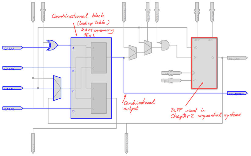
4. Testing (functional)
Organise a VHDL testbench Comp_24bit_tb.vhd filling in the empty skeleton supplied by Quartus Prime with some stimulus vectors representing comparison operations from the initial timing diagram.
5. Testing (gate-level)
In order to observe and measure worst cases, try to apply input vectors that require propagating signals through all the internal cascaded architecture.
6. Report
Follow this rubric for writing reports.
in this assignment you are solving a single project (one circuit architecture), even if you compare results from two target chips, at least five sheets of paper are required: (1) - (2) - (3) - (4) - (5).
Optional, you can experiment with other architectures for the same Comp_24bit, for instance, implementing the tree architecture for chaining comparators proposed as an application in this 74F85 chip datasheet. Which Comp_24bit will be faster?
| Home Term 23/24-Q2 Contact Products Electronic devices and companies Software Books Magazines Instruments DEE Library EETAC DEEL |

|
|
| Web activa des de 09/2001, @ F. J. Robert, J. Jordana. Web editat amb Microsoft Expression Web 4. El contingut és un complement als materials d'estudi del curs Circuits i Sistemes Digitals disponibles al campus digital Atenea. Llicència:Reconeixement 4.0 Internacional de Creative Commons |