|
|
Bachelor's Degree in Telecommunications Systems and in Network Engineering |
|
Legacy hardware: sPLD type 22V10 |
| Prototype specifications | Planning | Development and Test & Measurements |
Let us adapt the Counter_BCD_mod60 to a simple programmable logic device sPLD GAL22V10.
 |
|
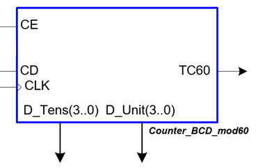
Fig. 1. Symbol of the basic up counter in BCD code modulo 60. |
There are two versions:
-
GAL22V10D programmed using specialised universal programmers like the TopMax-III from EE-Tools or this Chinese T76 model from XGecu. Lattice Semiconductor discontinued these sPLD chips by 2010. Microchip has its equivalent ATF22V10C in production.
-
ispGAL22V10C configured using four additional pins for the In-System re-Programmable Gate Array Logic (ispGAL) interface.
We will implement the basic features on the top design, such:
- Count enable switch (CE)
- Push-button for CLK edges or external oscillator connected throgh a header pin.
- TC60 LED indicator, terminal count, one pulse every 60 CLK's active risign edges.
- 8-output LED for counting in BCD units and tens.
Designing the counter reversible (UD_L) is not possible in a single sPLD, it does not contain enough logic esources.
7-segment displays can be added using extra sPLD's to implement the HEX_7seg_decoder to show the current counter count.
To check that our circuit works we can also use the Proteus simulator because this sPLD is modelled. It works simply attaching the output configuration file *.jed to the chip.
We will try to prototype the circuit in a standard protoboard programming the ispGAL22V10 using the ProtoGAL kit.
This is the time for reviewing the basic ideas on sPLD:
-Basics on sPLD.
- 22V10 architecture. Number of macrocells available for experimetation.
- How to program sPLD devices using the *.jed file.
- Proteus sPLD model.
- Electronic schematic: switches, LED, push-buttons, etc.
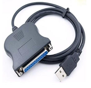
- Programmer. USB-parallel port adapter.
| Prototype specifications | Planning | Development and Test & Measurements |
We will follow the steps:
1. Develop and test functionally the application in Quartus Prime. Project folder:
C:\CSD\LEGACY\GAL\Counter_BCD_mod60_top\(files)
2. Copy the project's VHDL source files in the Window 7 VM for resynthesising using ispLEVER Classic from lattice Semiconductor. Assign pins and generate the configuration file *.jed. Project folders in Windows 7:
C:\CSD\GAL\Counter_BCD_mod60_top\(files)
3. Use Proteus to simulate the circuit functionality.
4. Use the ProtoGAL adapter to program the ispGAL device and prototype the experiment in a protoboard.
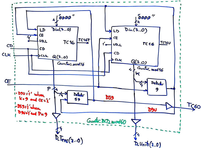
The following fully annotated plan C2 schematic is proposed for this adaptation to the FPGA board.
 |
|
Fig. 2. Counter_BCD_mod60_top adaptation. |
| Prototype specifications | Planning | Development and Test & Measurements |
Developing will be integrated with testing for each of the planned steps. We can only go ahead when the current steps works correctly.
1. Quartus Prime project
To complete the synthesis and functional testing of our application, we can develop the project using our current Quartus Prime EDA. At this stage we can select any target FPGA.
This are the two VHDL files required to translate our schematic in Fig. 2, the top Counter_BCD_mod60.vhd, and the component from our tutorial Counter_mod16.
 |
| Fig. 3. RTL view. |
Functional test in a VHDL testbench.
|
|
| Fig. 3. VHDL testbench. |
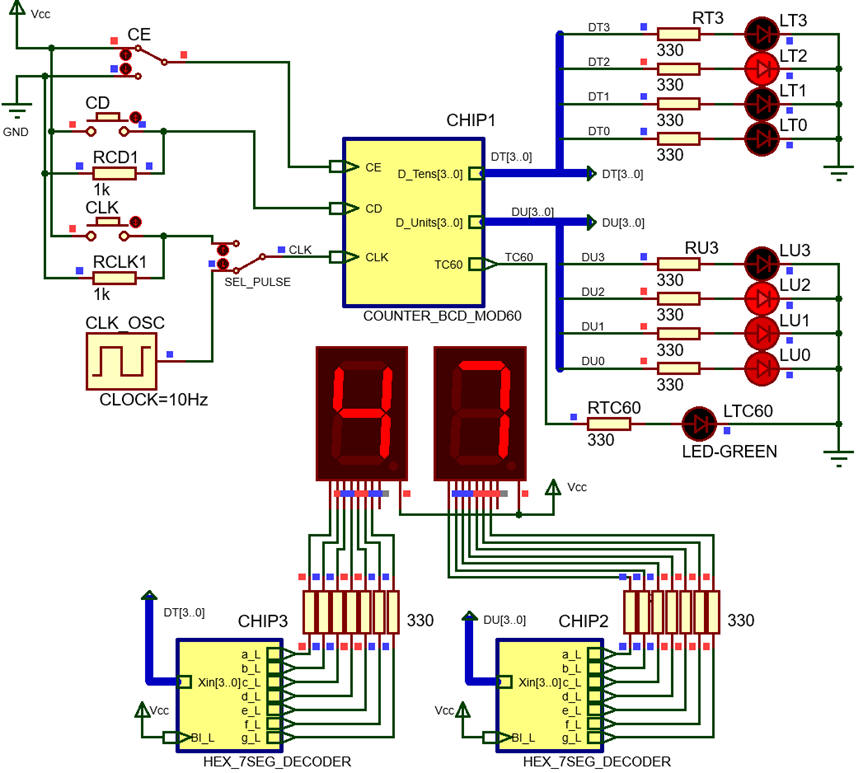
A more realistic test can be carried out in Proteus
 |
|
Fig. 4. Proteus circuit using three GAL 22V10 devices |
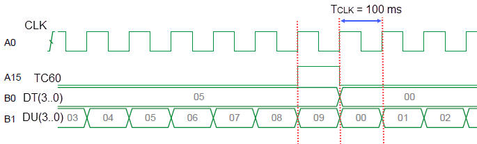
Testing the design using Proteus can be conveneintly done using its logic analyser instrument.
 |
|
Fig. 5. Proteus waveforms printed from its logic analyser instrument. |
2. ispLEVER Classic project. Pin assignment, configuration files
In this next stage, we can switch computers and tools to be able to target the obsolete sPLD device. Let us use the VM running Windows 7 and ispLEVER Classic EDA tool for synthesis. Use the shared drive between Windows 11 and Windows 7 to copy the VHDL source files into the virtual machine.
|
|
|
Fig. 6. Shared folder C:\CSD\VM_W7 between Windows 11 and the Window 7 VM. |
Let us start a new VHDL project for the sPLD including all the imported VHDL files. If we have to use the same environment for different legacy chips, it is convenient to organise the projects in separated folders. For instance:
C:\CSD\sPLD\Counter_BCD_mod60\(files)
This is the project to be opened in ispLEVER Classic Counter_BCD_mod60.zip.
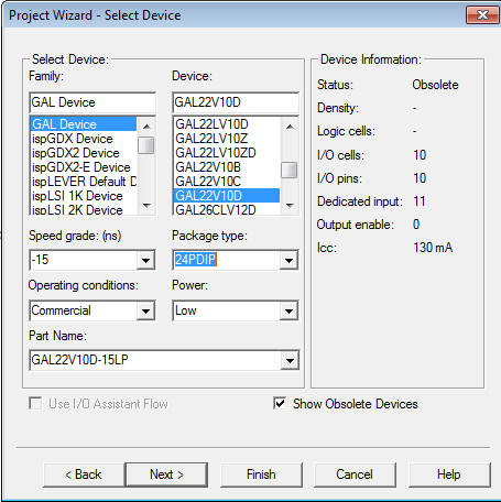
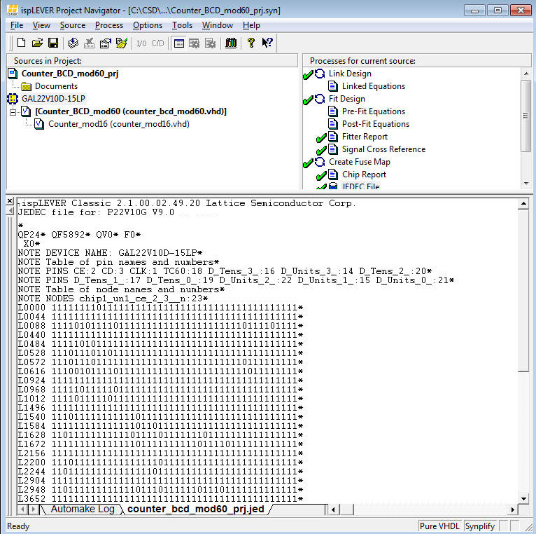
Once the project synthesised with no errors, the sPLD pins arfe assigned automatically as shown in Fig. 6. The final configuration file Counter_BCD_mod60.jed is also ready for programming the sPLD in the next step.
 |
|
Fig. 6. Pin assignments as reported by ispLEVER Classic. |
3B. Programming the ispGAL sPLD using the *.jed in a ProtoGAL board
To download the configuration file into the sPLD we have two options depending on the deveice model: GAL22V10 or ispGAL22V20.
| Fig. 7. ProtoGAL board. |


When ready, use the programmer tool installed in your Windows 11 computer to locate the target chip where to upload the configuration file. This is the sof file
|
|
|
Fig. 7. isProgrammer |
This sPLD configuration step can be executed directly from the Programmer as an standard-alone app. Let us use the *.jed file for the sPLD produced above in ispLEVER Classic. The GAL22V10 will be detected as shown in Fig. 8.
|
|
|
Fig. 8. Detecting the sPLD in the programmer. |
Check that the Protogal board works correctly running the Counter_BCD_mod60 configuration.
3A. Programming the standard sPLD using the *.jed in an universal programer
To download the configuration file into the sPLD we have two options depending on the deveice model: GAL22V10 or ispGAL22V20.
|
|
| Fig. 7. Universal programmer for the GAL22V10 using a Zero insertion force (ZIF) socket. |
When ready, use the programmer tool installed in your Windows 11 computer to locate the target chip where to upload the configuration file. This is the sof file
|
|
|
Fig. 7. isProgrammer |
This sPLD configuration step can be executed directly from the Programmer as an standard-alone app. Let us use the *.jed file for the sPLD produced above by ispLEVER Classic. The GAL22V10 will be detected as shown in Fig. 8.
|
|
|
Fig. 8. Detecting the sPLD in the programmer. |
Check that the Protogal board works correctly running the Counter_BCD_mod60 configuration.
| Home Term 26/27-Q1 Contact Products Electronic devices and companies Software Books Magazines Instruments DEE Library EETAC DEEL |

|
|
| Web activa des de 09/2001, @ F. J. Robert, Web editat amb Microsoft Expression Web 4. El contingut és un complement als materials d'estudi del curs Circuits i Sistemes Digitals disponibles al campus digital Atenea. Llicència:Reconeixement 4.0 Internacional de Creative Commons |